Conveniently-adjusted greenhouse for vegetables
The utility model relates to a vegetable greenhouse and convenient technology, which is applied in the field of vegetable greenhouses with convenient adjustment, and can solve the problems of inconvenient control of the ceiling, and achieve the effects of ensuring no self-slip, simplifying the structure, and being easy to adjust.
- Summary
- Abstract
- Description
- Claims
- Application Information
AI Technical Summary
Problems solved by technology
Method used
Image
Examples
Embodiment 1
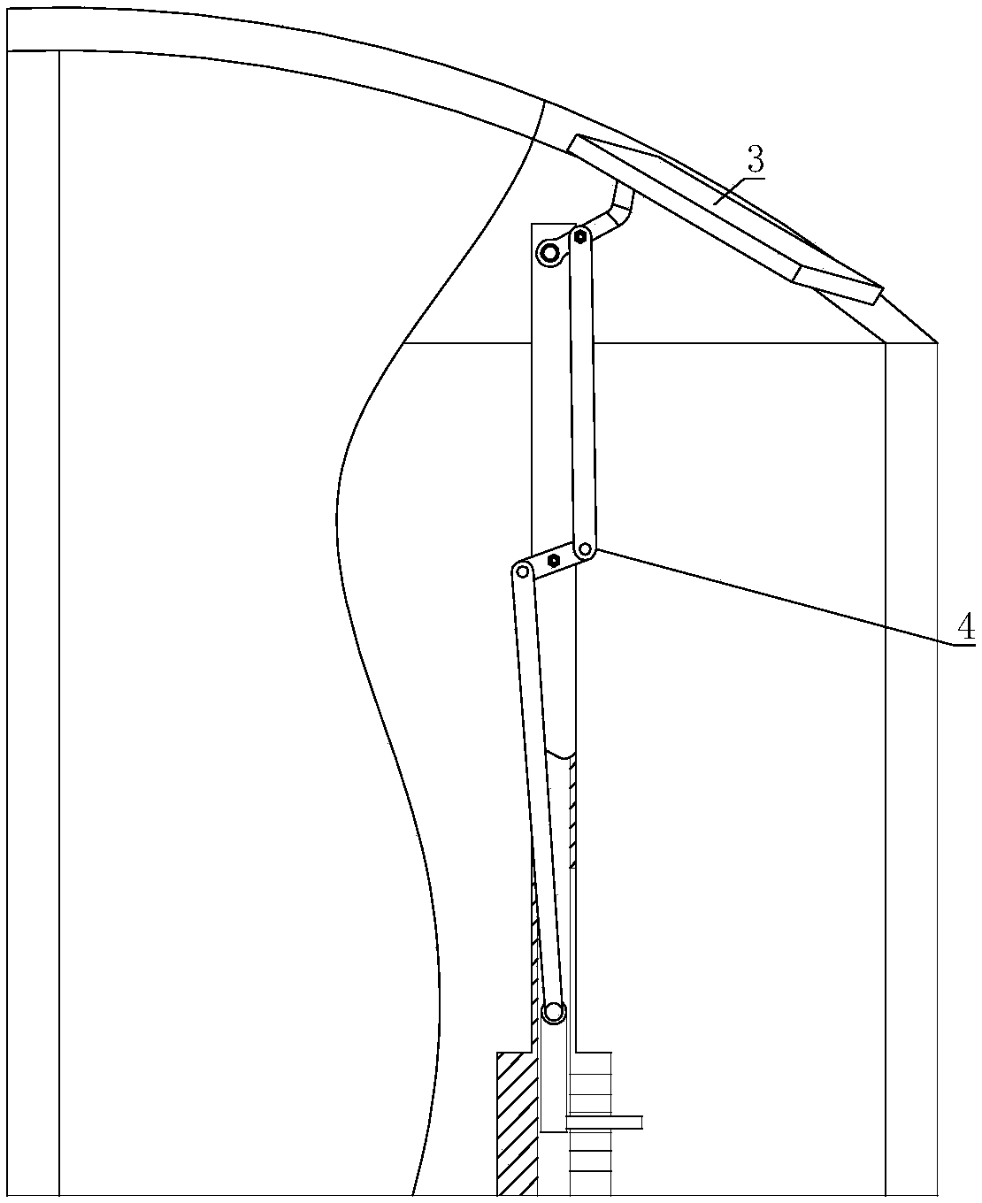
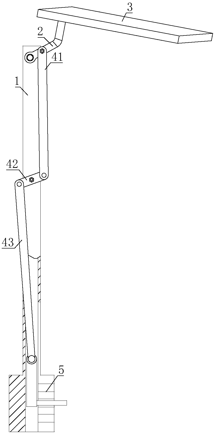
[0024] Such as figure 1 As shown, the present invention includes a greenhouse main body, a plurality of installation frames 1 are installed in the greenhouse main body, a rotating rod 2 is hinged on the top of the mounting frame 1, and a ceiling 3 is fixed on the other end of the rotating rod 2; a transmission mechanism 4 is hinged on the mounting frame 1 One end of the transmission mechanism 4 is hinged with the middle part of the rotating rod 2, and the other end of the transmission mechanism 4 is hinged with a gear mechanism 5 for changing or fixing the shape of the transmission mechanism 4, and the gear mechanism 5 is connected to the lower end of the mounting bracket 1.
[0025] When the shifting mechanism 5 is shifted to a different position, the transmission mechanism 4 acts, and the transmission mechanism 4 drives the ceiling 3 to tilt, so that the degree of opening and closing of the ceiling 3 is adjusted accordingly. Through the transmission of the transmission mecha...
Embodiment 2
[0027] On the basis of Embodiment 1, the transmission mechanism 4 includes a first connecting rod 41, one end of the first connecting rod 41 is hinged with the middle part of the rotating rod 2, and the other end of the first connecting rod 41 is hinged with a rocker 42. The other end of the rod 42 is hinged with a second connecting rod 43 , the middle part of the rocking rod 42 is hinged on the installation frame 1 , and the other end of the second connecting rod 43 is hinged with the gear shifting mechanism 5 .
[0028] When the shifting mechanism 5 pulls the second connecting rod 43 to move, the rocking bar 42 rotates accordingly, and the first connecting rod 41 moves under the driving of the rocking rod 42, so that the first connecting rod 41 can push the ceiling 3 to tilt. According to needs, when the shifting mechanism 5 is engaged in different gears, the steering of the rocker 42 changes, so that the first connecting rod 41 pushes the ceiling 3 to a proper position, whic...
Embodiment 3
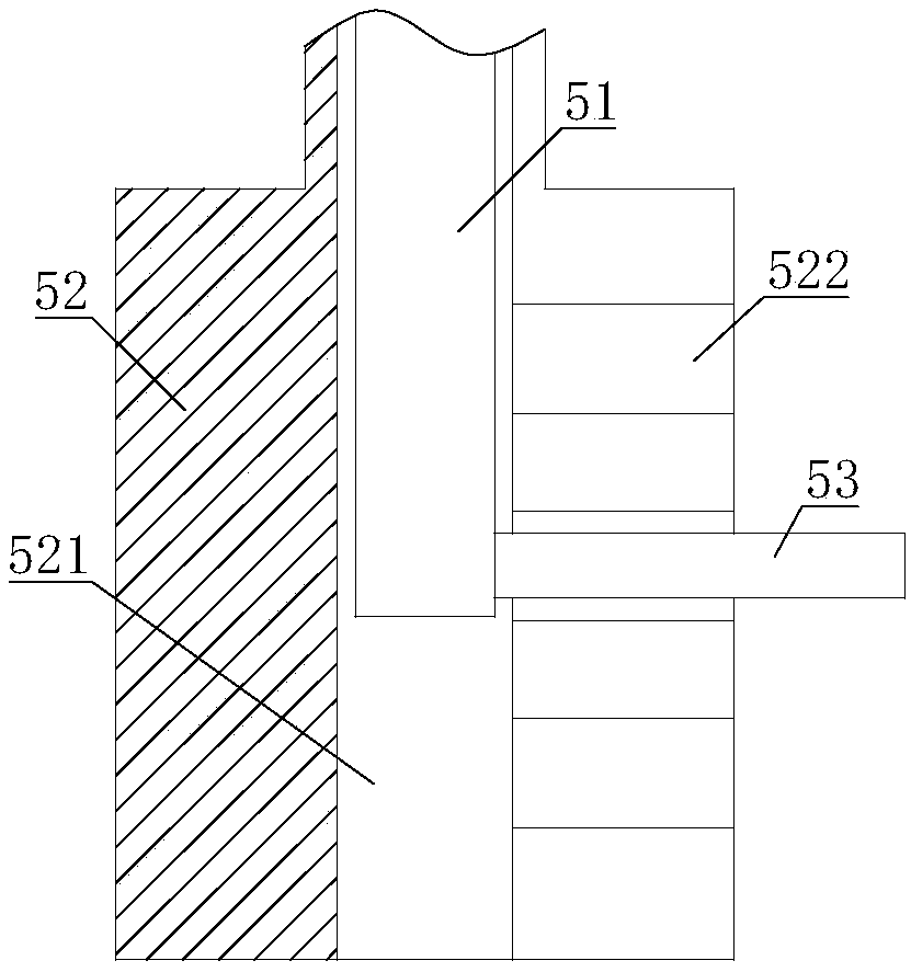
[0030] Such as figure 2 with image 3 As shown, on the basis of Embodiment 1 or Embodiment 2, the gear engaging mechanism 5 includes a slider 51, the lower end of the installation frame 1 is provided with a gear engaging sleeve rod 52, and the slider 51 is sleeved on the gear engaging sleeve rod 52. Inside; one end of the slider 51 is hinged with the transmission mechanism 4, and the other end of the slider 51 is fixed with a stop rod 53, and the side wall of the stop rod 52 is provided with a through groove 521 for the stop rod 53 to slide. 52 is also provided with several blocking grooves 522 , the through groove 521 communicates with the blocking grooves 522 , and the blocking rod 53 is engaged in one of the blocking grooves 522 .
[0031] When the blocking rod 53 is pulled, the slider 51 moves correspondingly, so that the transmission mechanism 4 drives the ceiling 3 to tilt accordingly. When the blocking rod 53 is snapped into the blocking groove 522, the degree of ope...
PUM
 Abstract
Description
Claims
Application Information
 - R&D Engineer
- R&D Manager
- IP Professional
- Industry Leading Data Capabilities
- Powerful AI technology
- Patent DNA Extraction
Browse by: Latest US Patents, China's latest patents, Technical Efficacy Thesaurus, Application Domain, Technology Topic, Popular Technical Reports.
© 2024 PatSnap. All rights reserved.Legal|Privacy policy|Modern Slavery Act Transparency Statement|Sitemap|About US| Contact US: help@patsnap.com


