A connection structure for motor output shaft and rotating shaft

A connection structure and output shaft technology, applied in the direction of electromechanical devices, electrical components, electric components, etc., can solve the problems of the shaft body beating, easy to break, loose connection between the motor output shaft and the rotating shaft, etc., to avoid shaft looseness and concentricity The effect of consistency and avoiding breakage

Active Publication Date: 2020-06-02
嘉兴市大得电器股份有限公司
View PDF8 Cites 2 Cited by
  • Summary
  • Abstract
  • Description
  • Claims
  • Application Information

AI Technical Summary

Problems solved by technology

[0005] In the prior art, the clamping device is generally used to connect the output shaft of the driving motor and the rotating shaft of the mechanical equipment, and then bolts are used to lock the connecting flange; there are also some connection methods that are mostly traditional keyway fit; there are also some special Local governments will adopt the connection method of key and tight double insurance. The above connection methods need to use external connectors to realize the connection between the motor output shaft and the rotating shaft, so there is a problem of loose connection between the motor output shaft and the rotating shaft , resulting in a connection gap between the two, causing the shaft to jump during transmission and easily broken

Method used


Image

  • A connection structure for motor output shaft and rotating shaft
  • A connection structure for motor output shaft and rotating shaft
  • A connection structure for motor output shaft and rotating shaft

Examples


Embodiment Construction

[0029] In order to make the technical means, creative features, goals and effects achieved by the present invention easy to understand, the following embodiments are combined with the accompanying drawings to elaborate on the present invention.

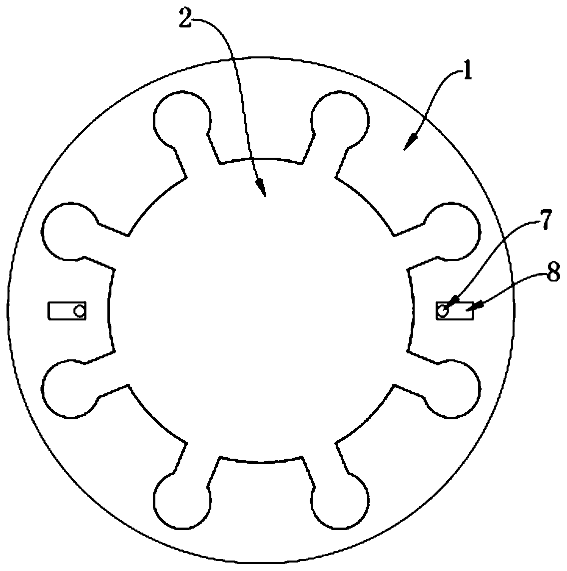
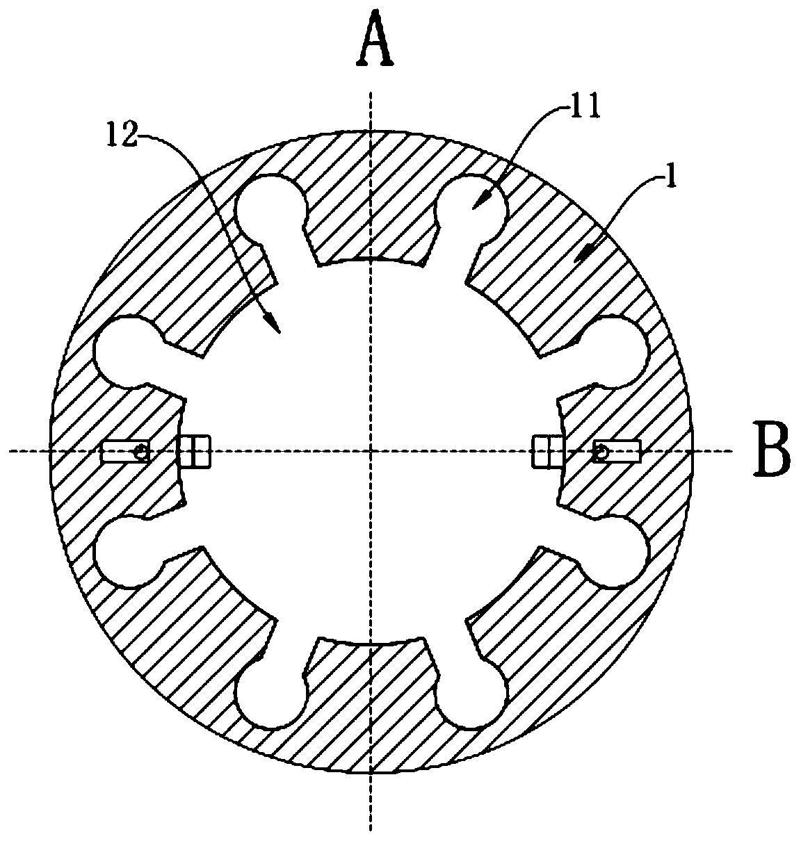
[0030] figure 1 It is a schematic diagram of the overall structure of the present invention, please combine figure 1 , shows a connection structure for the motor output shaft 1 and the rotating shaft 2, including the motor output shaft 1 and the rotating shaft 2, the rotating shaft 2 is embedded in the motor output shaft 1, and can also be the motor output shaft 1 embedded It is arranged in the rotating shaft 2. In this embodiment, preferably, the rotating shaft 2 is embedded in the output shaft 1 of the motor. A plurality of bumps 21 are arranged on the rotating shaft 2, and the bumps 21 are radially distributed along the axis of the rotating shaft 2. The motor output shaft 1 is provided with a circumferential limit groove 11 matche...


PUM


Abstract

The invention discloses a connecting structure for a motor output shaft and a rotary shaft. The connecting structure comprises a motor output shaft and a rotary shaft. The rotary shaft is embedded inthe motor output shaft and is provided with a plurality of bumps distributed in a radial shape along the axis of the rotary shaft. The motor output shaft is provided with a circumferential stopping slot that cooperates with the bumps. A first stopping assembly is disposed on the motor output shaft. A first groove is arranged on the rotary shaft and cooperates with the first stopping assembly. A second stopping assembly is arranged on the rotary shaft. The motor output shaft is provided with a wavy second groove arranged in the axial direction and matching the second stopping assembly. The connecting structure does not require an external connector, can directly realize the clamping connection between the motor output shaft and the rotary shaft of mechanical equipment. The axial and circumferential dual restrictions guarantee the concentricity during the assembly of the motor output shaft and the rotary shaft. The connecting structure is good in stability and avoids shaft loosening.

Description

technical field [0001] The invention relates to the technical field of connecting structures, in particular to a connecting structure used for a motor output shaft and a rotating shaft. Background technique [0002] Motors are widely used as driving power in industrial production. Motors are often connected to the rotating shaft of mechanical equipment and drive the rotating shaft to rotate, driving the operation of the entire mechanical equipment. When in use, it is very important to ensure that the concentricity of the motor output shaft and the rotating shaft is consistent. [0003] When the assembly concentricity between the output shaft of the motor and the rotating shaft is guaranteed to be good, the output shaft of the motor bears only the rotational force, and the operation will be very smooth without pulsation. When it is not concentric, the output shaft of the motor also bears the radial force from the rotating shaft. The action of this radial force will force th...

Claims


Application Information

Patent Timeline
Patent Type & Authority Patents(China)
IPC IPC(8): H02K7/00
CPCH02K7/003
Inventor 李洪毅
Owner 嘉兴市大得电器股份有限公司
Why Eureka
Try Eureka