
Automatic Settlement System and Settlement Method Based on Optical Surface Imaging

An automatic settlement and smooth technology, applied in the field of settlement system, can solve the problems of slow speed and complicated image comparison method, and achieve the effect of improving settlement speed, reducing secondary workload and reducing calculation time.

Active Publication Date: 2020-10-23
SUZHOU YOUHAN INFORMATION TECH CO LTD
View PDF7 Cites 0 Cited by
  • Summary
  • Abstract
  • Description
  • Claims
  • Application Information

AI Technical Summary

Problems solved by technology

The image comparison method is to take pictures of the products, compare them with the pictures in the image library, and find the corresponding products for calculation. The image comparison method is complicated and slow

Method used


Image

  • Automatic Settlement System and Settlement Method Based on Optical Surface Imaging
  • Automatic Settlement System and Settlement Method Based on Optical Surface Imaging
  • Automatic Settlement System and Settlement Method Based on Optical Surface Imaging

Examples


Embodiment 1

[0038] The invention discloses an automatic settlement system based on smooth imaging, which includes more than two smooth imaging devices, a camera device, a commodity transmission device, and a calculation and analysis unit;

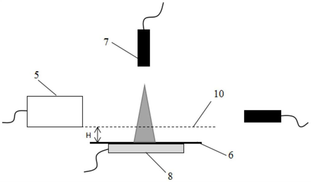
[0039] The smooth imaging device includes a line light source, a lens, and an area array camera. The plane illuminated by the line light source, the lens surface, and the area array camera plane intersect in a line; the smooth imaging device is installed on the commodity One end or side of the conveying device is higher than the commodity conveying device; the camera device for taking pictures of commodities is installed on any one or more parts of the commodity conveying device except the bottom; The cross-sectional profile, cross-sectional area, and photo information obtained by the camera device are used to match products. An array sensor with LEDs and photodetectors arranged alternately is installed on the side of the product conveying device to ob...

Embodiment 2

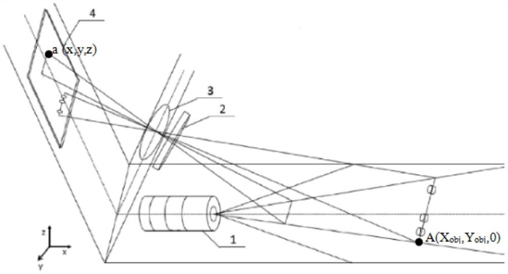
[0054] figure 1 It is a schematic diagram of the structure of the smooth imaging device in the automatic settlement system. As shown in the figure, the optical surface imaging device includes a light source 1 , a filter 2 , a lens 3 , and an area array camera 4 . The plane illuminated by the light source, the lens surface, and the plane of the area array camera intersect in a line; when the line light source 1 illuminates an object on the plane, the light is reflected by the object, and the reflected light is imaged on the surface through the filter 2 and the lens 3 The shape of the corresponding position of the array camera 4 is the contour of the object illuminated by the line light source, and then the area of ​​the contour of the object can be calculated. The plane illuminated by the light source is a point A(X obj ,Y obj ,0), and the image point on the surface plane of the area array camera, that is, the image plane, is a(x, y, z).

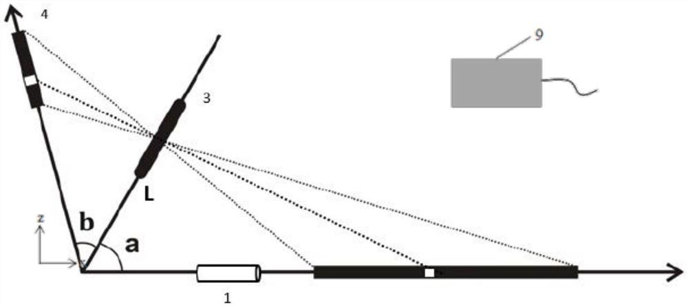
[0055] figure 2 It is a side vie...


PUM


Abstract

The invention discloses an automatic settlement system and settlement method based on smooth imaging, comprising a smooth imaging device, an imaging device, a commodity conveying device, and a calculation and analysis unit; the smooth imaging device includes a line light source, a lens, and an area array camera , the plane illuminated by the line light source, the lens surface, and the plane of the area array camera intersect in a line; the smooth imaging device is installed at one end or side of the commodity conveying device and is higher than the commodity conveying device; photographing the commodity The photographing device is installed on multiple parts of the commodity conveying device except the bottom; the calculation and analysis unit matches the cross-sectional profile and cross-sectional area obtained by the optical imaging device with the photo information obtained by the photographing device. The invention adopts smooth imaging and image matching technology, and does not need to add additional marks to the products; first compares the cross-sectional images of the products, and then compares the photos of each side of the products, which reduces the calculation time of image matching compared with directly comparing the color photos of the products.

Description

technical field [0001] The invention relates to the technical field of settlement systems, in particular to an automatic settlement system and settlement method based on smooth imaging and image matching. Background technique [0002] Unmanned supermarkets are a new trend in the future development of the retail industry. In the operation of unmanned supermarkets, settlement and cash register is the most critical link. Currently, unmanned supermarket settlement mainly adopts two technologies: RFID (Radio Frequency Identification, radio frequency identification) technology and image matching technology. RFID technology is to use the tags on the products to identify the products, so as to calculate the price of the products. When using RFID technology, it is necessary to attach RFID tags to the products, which increases the secondary workload. The image comparison method is to take pictures of commodities, compare them with the pictures in the image library, and find the corr...

Claims


Application Information

Patent Timeline
Patent Type & Authority Patents(China)
IPC IPC(8): G07G1/00G06K9/62
CPCG07G1/0036G06F18/22
Inventor 何赛灵
Owner SUZHOU YOUHAN INFORMATION TECH CO LTD
Learn More