Caliper

A logging tool and outer casing technology, which is applied in the direction of wellbore/well components, measurement, earthwork drilling and production, etc. It can solve problems such as inaccurate data, affecting the progress of the project, and complex structures.

Inactive Publication Date: 2020-10-23
BAYIN GUOLENG TECH COLLEGE
View PDF13 Cites 0 Cited by
  • Summary
  • Abstract
  • Description
  • Claims
  • Application Information

AI Technical Summary

Problems solved by technology

[0004] After the device is lowered down the well and the measuring arm of the instrument is pushed away by the pusher, the four measuring arms of the instrument can be retracted freely with the change of the well diameter, and the four logging arms independently drive the potentiometer to move. The effect is good, and the accuracy of reflecting the change of the borehole wall diameter is relatively high. However, the expansion and contraction of the logging arm of this device are all carried out by the motor, the structure is complex, and the operation is cumbersome, the reliability is poor, and the energy consumption is low. At the same time, due to the poor stability of the motor and the transmission part, it is prone to failure, which will make the detected data inaccurate and affect the progress of the project

Method used


Image

  • Caliper
  • Caliper
  • Caliper

Examples


Embodiment 1

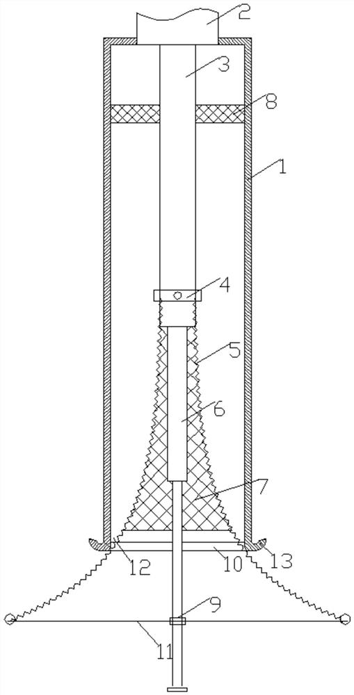
[0021] like figure 1 As shown, the caliper logging instrument includes an outer sleeve 1 and a main telescopic rod 3, the main telescopic rod 3 is installed in the outer sleeve 1, the main telescopic rod 3 is coaxial with the outer sleeve 1, and the main telescopic rod 3 is coaxial with the outer sleeve 1. The rod 3 is controlled by the telescopic controller 2; the telescopic controller 2 is installed on the top of the outer sleeve 1; there is a guide block 8 inside the outer sleeve 1, and there are through holes in the guide block 8 for The main telescopic rod 3 passes through; the lower end of the outer sleeve 1 is an open end 10;

[0022] The outer wall of the main telescopic rod 3 is equipped with a fixed ring 4; it also includes a plurality of elongated elastic reeds 5, one end of the reed 5 is fixed on the fixed ring 4, and the other end is equipped with a ball 12; The reeds 5 are distributed symmetrically around the main telescopic rod 3, and the reeds 5 are arc-shaped...

Embodiment 2

[0028] In order to ensure the stability of each reed 5 being folded and released, on the basis of Embodiment 1, the following technical features are also included:

[0029] The lower end of the main telescopic rod 3 is connected to the central rod 6, and the central rod 6 is covered with a collar 9, and the collar 9 can slide on the central rod 6; each of the balls 12 is respectively connected to a Root elastic cord 11, the other end of elastic cord 11 is fixed on the collar 9.

[0030] The elastic cord 11 can constrain the reed 5 to stretch out too long, which will affect the measurement effect. And contribute to the retraction of reed 5 and ball 12. Elastic rope 11 can also keep each reed 5 to protrude the same as far as possible in addition, and central rod 6 can be positioned at the center line of well as far as possible, guarantees the accuracy of measurement.

Embodiment 3

[0032] When used to measure the position close to the bottom of the well, since the reed 5 is stretched out, it is turned outwards, and the ball 12 is also close to the bottom of the well, in order to prevent the center rod 6 from pressing against the bottom of the well, the ball 12 cannot be attached to the bottom of the well. Therefore, in the technical solution of Embodiment 2, the central rod 6 is designed to be a telescopic rod, including multiple sleeve rods with gradually changing diameters. set of poles. like image 3 As shown, when hitting the bottom, the central rod 6 is retracted to ensure that the ball 12 is attached to the bottom of the well for measurement.


PUM


Abstract

The invention relates to the technical field of petroleum logging, in particular to a well diameter logging instrument. A main telescopic rod is mounted in an outer sleeve; the lower end of the outersleeve is open; a fixed ring is mounted on the outer wall of the main telescopic rod; the well diameter logging instrument further comprises a plurality of long-strip-shaped elastic spring pieces; oneends of the spring pieces are fixed to the fixed ring, and balls are mounted at the other ends of the spring pieces; the multiple spring pieces are symmetrically distributed on the periphery of the main telescopic rod; each spring piece is of an arc-shaped structure, the convex faces of the spring pieces face the main telescopic rod, and the balls are closely attached to the inner wall of the outer sleeve under the elastic force of the spring pieces; and displacement sensors are mounted on the balls. The balls are pushed out through the elastic force of the spring pieces, measurement is conducted at any time, other external force does not need to be supplied, the spring pieces are easy to converge and separate, a fault is not liable to occur; and measurement operation is easy, reliabilityis good, stability is good in the measurement process, and measurement date are quite accurate.

Description

technical field [0001] The present application relates to the technical field of petroleum well logging, in particular to a caliper logging instrument. Background technique [0002] In the process of oil production, casing wear is unavoidable in oilfields. During the implementation of various oil production measures, the pressure imbalance between wells and layers will be caused, which will intensify fault activity and mudstone water absorption expansion. A series of casing damage phenomena such as chemical corrosion, etc., make the casing wear, corrosion, damage and other deformations. At present, using the caliper logging tool to measure the casing technology is one of the effective means to detect casing damage. The caliper logging tool can reflect the wear, corrosion, damage and other deformation of the casing by measuring the inner diameter of the casing. [0003] Existing logging devices generally use a multi-arm caliper logging tool, which is equipped with a measurin...

Claims


Application Information

Patent Timeline
Patent Type & Authority Patents(China)
IPC IPC(8): E21B47/08
CPCE21B47/08
Inventor 闫玲玲宋跃海
Owner BAYIN GUOLENG TECH COLLEGE
Why Eureka
Try Eureka