Pyranometer with forced airflow

A technology for pyranometers and exhaust ducts, applied in the field of pyranometers, which can solve problems such as inability to obtain main power

Active Publication Date: 2021-05-07
HUKSEFLUX HLDG BV
View PDF4 Cites 0 Cited by
  • Summary
  • Abstract
  • Description
  • Claims
  • Application Information

AI Technical Summary

Problems solved by technology

[0018] Low power consumption is essential for the use of pyranometers as these instruments are often deployed in remote locations where mains power is not available

Method used


Image

  • Pyranometer with forced airflow
  • Pyranometer with forced airflow

Examples


Embodiment Construction

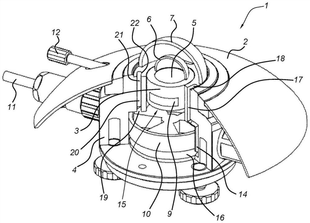
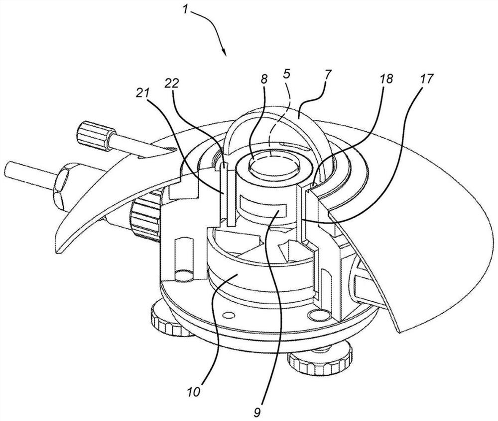
[0046] figure 1 A pyranometer 1 is shown with a substantially closed housing 2 surrounding a detector body 3 , a cylindrical metal wall 4 and a thermal sensor 5 . The sensor 5 is covered by an inner dome 6 , which is in thermal contact with the top surface of the body 3 , and an outer dome 7 , which is in thermal conductive contact with the top surface of the detector wall 4 .

[0047] The ventilator space 15 enclosed by the cylindrical wall 4 accommodates a micro-ventilator 10, which may have, for example, a diameter of 3.5 cm and a power of 0.5W. The underside 16 of the ventilator space 15 is in contact with the outlet 14 of the exhaust duct 17 , the inlet 18 of which is located in the space between the two domes 6 , 7 . The upper side 19 of the ventilation space 15 is in contact with the inlet 20 of the air supply duct 21 , the outlet 22 of which is located in the space between the two domes 6 , 7 . The inlet 18 and outlet 22 are located at diametrically opposed positions...


PUM


Abstract

The invention relates to a pyranometer (1) having a housing (2), a sensor (5) inside said housing, an internal window (6) and a dome-shaped external window (7), an air inlet duct (21) and exhaust duct (17), both windows cover the sensor (5), the intake duct (21) and exhaust duct (17) extend in the housing and terminate at the said outer window (7) for allowing air to flow through said space from said intake duct to said exhaust duct, the invention is characterized in that said housing is substantially closed so as not to external airflow is allowed to enter the housing (2), and includes a ventilation device (10), the intake duct (21) is in fluid communication with the high pressure side of the ventilation device (10), the exhaust duct (17) In fluid communication with the low pressure side of the ventilation device (10), the air blown into the space below the external window (7) is heated by the energy of the ventilation device and optionally by an additional electric heater.

Description

technical field [0001] The present invention relates to a pyranometer having a housing, a pyroelectric sensor located within the housing, an interior window and an exterior dome-shaped window, an intake duct and an exhaust duct, both windows covered the sensor; an intake duct and an exhaust duct extending in the housing and terminating in a space confined by the exterior window for passing air through the space from the intake duct to the exhaust catheter. Background technique [0002] Such a radiation detection device in the form of a pyranometer is known from US Pat. No. 3,876,880. This publication describes a pyranometer in which an external pump and heat exchanger provide cooling airflow to the probe housing to cool the inner and outer domes. Additionally, external fans direct air flow across the dome for improved radiometric accuracy. [0003] In commonly known pyranometers (eg model SR11, sold by Hukseflux Thermal Sensors B.V., Delft, Netherlands), inner and outer g...

Claims


Application Information

Patent Timeline
Patent Type & Authority Patents(China)
IPC IPC(8): G01J1/42G01J5/04G01J5/02
CPCG01J1/42G01J1/4204G01J2001/4285G01J5/05G01J5/051G01J5/042
Inventor E·R·霍克萨马C·J·范登博斯
Owner HUKSEFLUX HLDG BV
Why Eureka
Try Eureka