
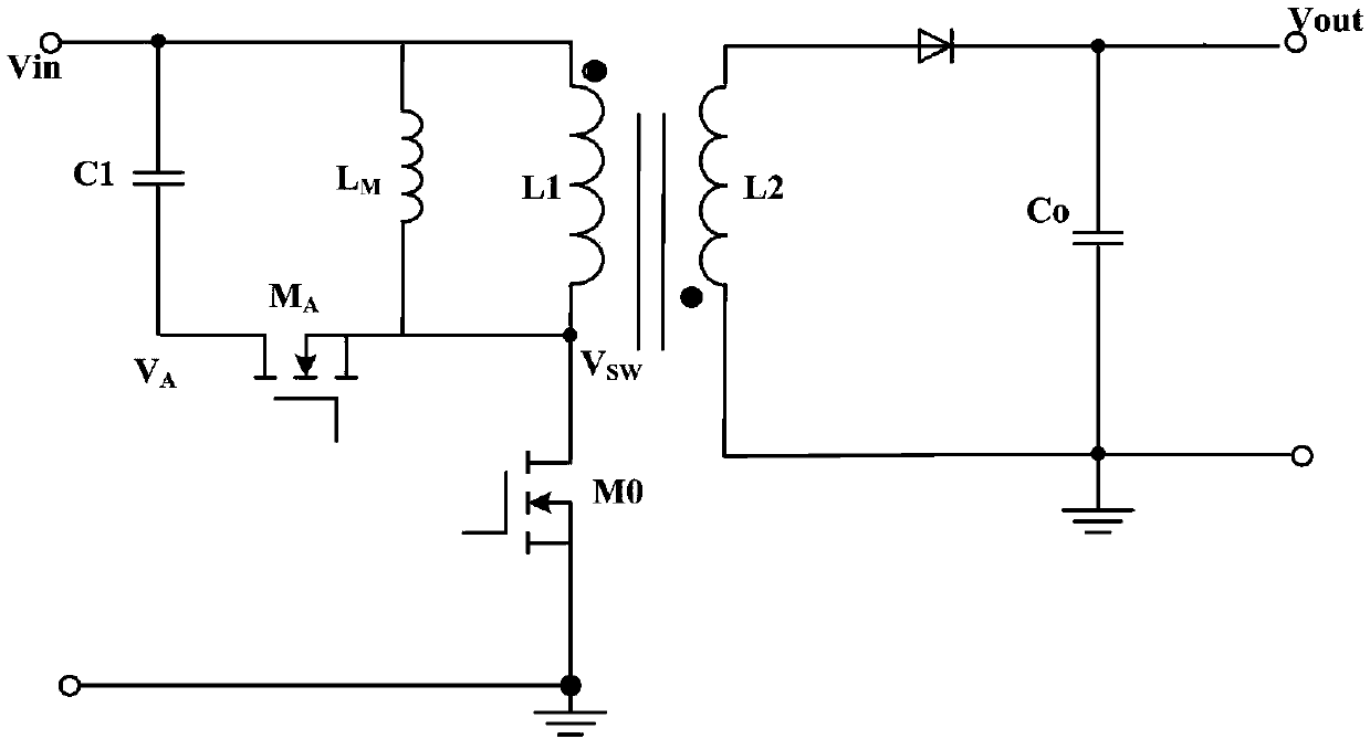
Flyback active clamping circuit and control method thereof

A technology of clamping circuit and voltage, applied in the direction of control/regulation system, electrical components, adjusting electric variables, etc., can solve the problems of precise control without switching tube MA, increase of conduction loss, etc., and achieve reduction of conduction loss and decrease The effect of turn-on loss

Active Publication Date: 2018-02-23
JOULWATT TECH INC LTD
View PDF5 Cites 8 Cited by
  • Summary
  • Abstract
  • Description
  • Claims
  • Application Information

AI Technical Summary

Problems solved by technology

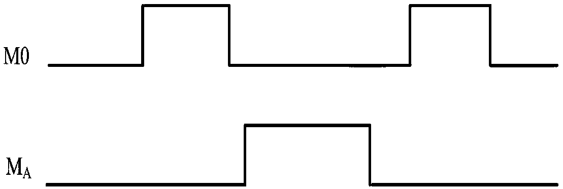
[0005] L M is the magnetizing inductance in the primary winding, the prior art utilizes figure 2 The control method in the control method controls the turn-off of the switch tube MA, because there is no precise control for the turn-off time of the switch tube MA before the main power switch tube M0 is turned on, which may cause L M The technical problem of increasing the conduction loss due to excessive negative current

Method used


Image

  • Flyback active clamping circuit and control method thereof
  • Flyback active clamping circuit and control method thereof
  • Flyback active clamping circuit and control method thereof

Examples


Embodiment Construction

[0028] Preferred embodiments of the present invention will be described in detail below with reference to the accompanying drawings, but the present invention is not limited to these embodiments. The present invention covers any alternatives, modifications, equivalent methods and schemes made within the spirit and scope of the present invention.

[0029] In order to provide the public with a thorough understanding of the present invention, specific details are set forth in the following preferred embodiments of the present invention, but those skilled in the art can fully understand the present invention without the description of these details.

[0030] In the following paragraphs the invention is described more specifically by way of example with reference to the accompanying drawings. It should be noted that all the drawings are in simplified form and use inaccurate scales, which are only used to facilitate and clearly assist the purpose of illustrating the embodiments of t...


PUM


Abstract

The invention discloses a flyback active clamping circuit and a control method thereof. The flyback active clamping circuit comprises a flyback switch power supply, a first capacitor and a first switching tube. One terminal of the first capacitor is connected to a high potential terminal of an input power supply. The other terminal of the first capacitor is connected to the first terminal of the first switching tube. The second terminal of the second switching tube is connected to a common terminal of a main power switching tube and an primary side winding. A switching off moment of the firstswitching tube is adjusted according to conduction of the main power switching tube, switching off time of the first switching tube and voltage on two terminals of a magnetized inductor The flyback active clamping circuit and the control method thereof can reduce loss of turn-on of the main power switching tube and can reduce conduction loss.

Description

technical field [0001] The invention relates to the technical field of power electronics, in particular to a flyback active clamping circuit and a control method thereof. Background technique [0002] A flyback switching power supply is an isolated switching power supply that is widely used in alternating current direct current (AC / DC) and direct current direct current (DC / DC) conversion, and provides insulating isolation between the input stage and the output stage. The flyback switching power supply includes a main power switch tube, a transformer and a secondary rectifier tube, the transformer includes a primary winding and a secondary winding, the main power switch tube is connected to the primary winding, and the secondary rectifier tube It is connected with the secondary winding, and the switching state of the main power switch tube is controlled by the primary side control circuit, and the secondary rectifier tube located on the secondary side conducts freewheeling af...

Claims


Application Information

Patent Timeline
Patent Type & Authority Applications(China)
IPC IPC(8): H02M3/335
CPCH02M3/33569H02M1/0058Y02B70/10
Inventor 黄必亮周逊伟
Owner JOULWATT TECH INC LTD
Learn More