
Aircraft

An aircraft and antenna controller technology, applied in the field of aircraft, can solve the problems of high cost of aircraft and high requirements for control modules, and achieve the effects of increasing coverage, reducing costs, and improving signal transmission capabilities

Inactive Publication Date: 2018-02-23
BYD CO LTD
View PDF8 Cites 0 Cited by
  • Summary
  • Abstract
  • Description
  • Claims
  • Application Information

AI Technical Summary

Problems solved by technology

However, this method has high requirements on the control module of the main board, and the control module needs to have the function of switching antennas, resulting in a relatively high cost of the aircraft.

Method used


Image

  • Aircraft
  • Aircraft
  • Aircraft

Examples


Embodiment Construction

[0024] Embodiments of the invention are described in detail below, examples of which are illustrated in the accompanying drawings. The embodiments described below by referring to the figures are exemplary and are intended to explain the present invention and should not be construed as limiting the present invention.

[0025] The aircraft 100 according to the embodiment of the present invention will be described in detail below with reference to the accompanying drawings.

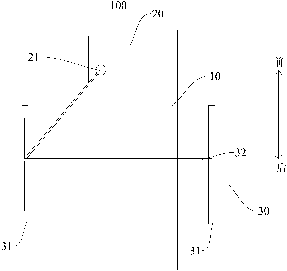
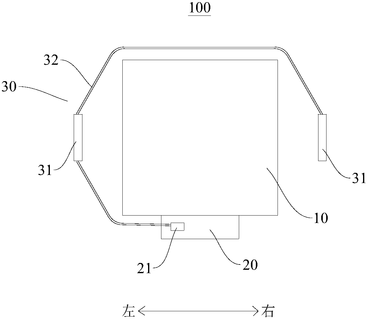
[0026] Such as figure 1 and figure 2 As shown, the aircraft 100 according to the embodiment of the present invention may include: a body 10 and an antenna assembly 30, the body 10 may be provided with an antenna controller 20, the antenna controller 20 is provided with an access port 21, and the antenna assembly 30 includes a plurality of antennas 31 , a plurality of antennas 31 are sequentially connected by connecting wires 32 , the plurality of antennas 31 are arranged around the body 10 , and the anten...


PUM


Abstract

The invention discloses an aircraft. The aircraft comprises: a body, wherein an antenna controller is arranged in the body, and an access entry is formed in the antenna controller; and an antenna assembly, wherein the antenna assembly comprises a plurality of antennae, the antennae are connected in sequence through a connecting line, the antennae surround the body, and the antenna at one end is connected with the access entry. The antenna controller can be connected with the plurality of antennae in the antenna assembly through the access entry, so that the quantity of the access entry can bereduced, the antenna controller does not need to switch the using states of the antennae, and the cost of the aircraft can be reduced accordingly. Moreover, the antennae surround the body to effectively expand the coverage range of radiation signals of the antennae, so that a weak-signal area can be reduced or even avoided, the signal transmission capability of the aircraft can be improved, and the image transmission reliability of the aircraft can be improved.

Description

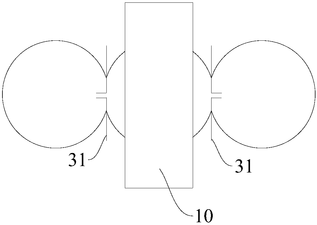
technical field [0001] The invention relates to an aircraft. Background technique [0002] When the aircraft is flying in the air, it needs to rotate 360 ​​degrees to facilitate shooting from all angles. In the structural design of the aircraft, the antenna is often installed on one side of the aircraft. The whole fuselage, which is equivalent to a large metal, has a strong reflection effect on the antenna, so that the pattern radiated by the antenna is close to a half circle. The antenna has radiation only on the side with the antenna, and the antenna signal on the other side of the fuselage facing the antenna will be very weak, even close to zero. Metal can absorb and reflect the radiation of the antenna. For example, if an antenna has a spherical radiation pattern, the antenna is regarded as a point located at the center of the sphere, and a metal plate is placed on one side of the antenna. When the area of ​​the metal plate When it is larger than the area of ​​the ant...

Claims


Application Information

Patent Timeline
IPC IPC(8): B64C39/02H01Q1/28
CPCB64C39/02H01Q1/285
Inventor 陈亚娟李振义江奕辰王发平
Owner BYD CO LTD
Learn More