Cooling liquid filtering device for multifunctional turning lathe

A technology of filtering device and cooling liquid, applied in the field of lathes, can solve the problems of inconvenient cleaning, inconvenient cleaning operation, large volume of the collecting trough, etc., and achieve the effects of easy collection of chips and garbage, good lighting effect, and easy collection.

Pending Publication Date: 2018-02-23
平湖智铂自动化设备股份有限公司
View PDF0 Cites 4 Cited by
  • Summary
  • Abstract
  • Description
  • Claims
  • Application Information

AI Technical Summary

Problems solved by technology

[0002] During the use of the lathe, there will be chip garbage. The chip garbage needs to be cleaned in time after use to ensure the cleanliness of the lathe. The collecting tank at the bottom of the lathe for collecting garbage can collect the chip garbage during the use of the lathe. The collected chips need to be treated in a unified way. The current collection tank has some shortcomings in the process of use. The volume of the collection tank is large, occupying space resources, the quality of the collection tank is heavy, and it is inconvenient to clean. There is no chute on the side wall of the collecting tank, so it is difficult to move. The chip waste is usually mixed with the coolant. The coolant is very easy to get dirty, and it cannot be cleaned when cleaning the chip waste. The chip waste is wet and easy to get dirty when cleaning the chip waste. The ground is dirty or the clothes of the cleaning personnel are dirty, and the collection tank is located under the lathe, the light is relatively dark, the cleaning operation is very inconvenient, and the practicability is poor

Method used


Image

  • Cooling liquid filtering device for multifunctional turning lathe
  • Cooling liquid filtering device for multifunctional turning lathe
  • Cooling liquid filtering device for multifunctional turning lathe

Examples


Embodiment

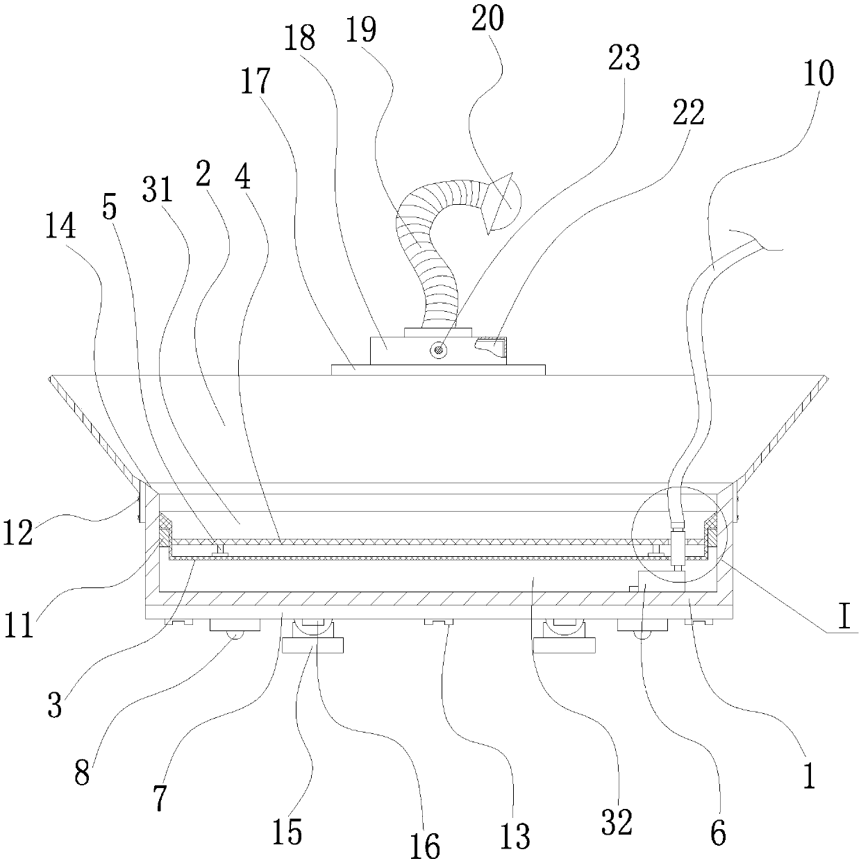
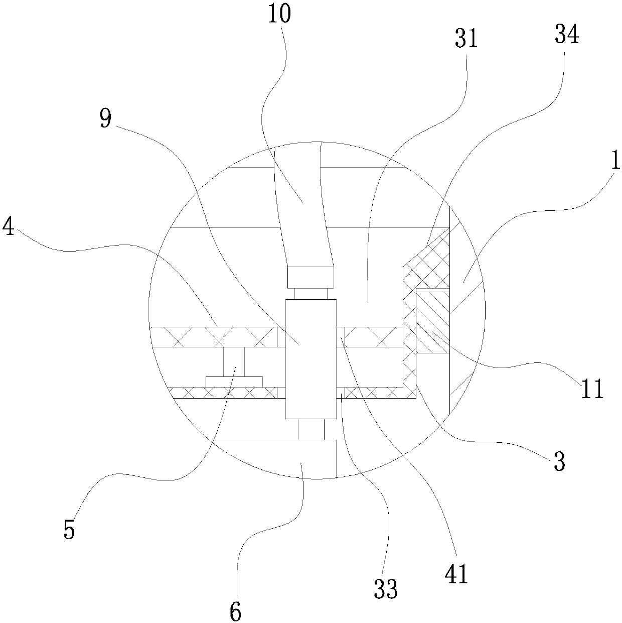
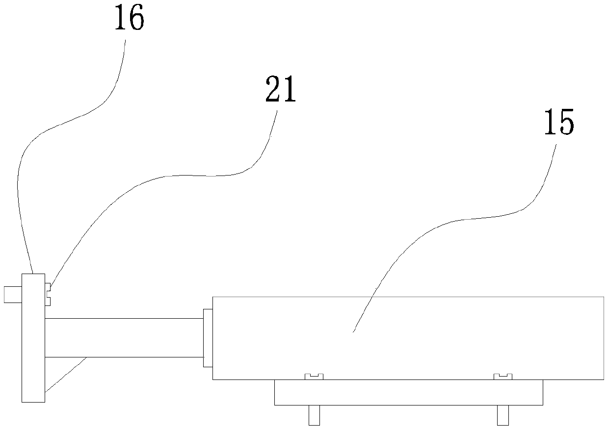
[0022] Example: such as figure 1 , figure 2 and image 3 As shown, a coolant filter device for a multifunctional lathe includes a collection tray 1, the upper end of the collection tray 1 is sleeved with a garbage guide cover 2, and the garbage guide cover 2 is detachably connected to the collection tray 1; The inner wall surface of the collection tray 1 is integrally provided with a positioning convex ring 11, a first filter net 3 is suspended on the positioning convex ring 11, and a filter net groove 31 is arranged in the middle of the first filter net 3 , there is a cooling liquid collecting cavity 32 between the lower end surface of the first filter screen 3 and the inner bottom surface of the collecting tray 1, and a second filter screen 4 is arranged in the filter screen groove 31, and the second filter screen A number of legs 5 are fixedly arranged on the lower end surface of 4; a water pump 6 is arranged in the cooling liquid collection cavity 32, and a cooling liqu...


PUM


Abstract

The invention relates to a cooling liquid filtering device for a multifunctional lathe, which comprises a collection tray, a garbage guide cover is sleeved on the upper end of the collection tray, a first filter screen is suspended on a positioning convex ring of the collection tray, and the lower end of the first filter screen is There is a cooling liquid collection chamber, a second filter screen is arranged in the filter mesh groove, a water pump is arranged in the cooling liquid collecting chamber, a cooling liquid delivery pipe is arranged on the liquid outlet of the water pump, and a cooling liquid conveying pipe is arranged on the bottom plate of the collecting pan. A plurality of roller devices are provided; several drive cylinders are provided at the rear end of the collection tray; a lighting device installation plate is welded at the rear end of the garbage guide cover, and a lamp holder is detachably arranged on the installation board of the lighting device, and a lamp holder is welded on the upper end of the lamp holder. The first stainless steel snakeskin tube, the first stainless steel snakeskin threaded connection has an LED lighting lamp. The above technical scheme has reasonable structural arrangement, simple structure, multiple functions, easy collection of cuttings and garbage, clean cleaning, clean cooling liquid filtration and lighting function, and good practicability.

Description

technical field [0001] The invention belongs to the technical field of lathes, and in particular relates to a coolant filter device for a multifunctional lathe. Background technique [0002] During the use of the lathe, there will be chip garbage. The chip garbage needs to be cleaned in time after use to ensure the cleanliness of the lathe. The collecting tank at the bottom of the lathe for collecting garbage can collect the chip garbage during the use of the lathe. The collected chips need to be treated in a unified way. The current collection tank has some shortcomings in the process of use. The volume of the collection tank is large, occupying space resources, the quality of the collection tank is heavy, and it is inconvenient to clean. There is no chute on the side wall of the collecting tank, so it is difficult to move. The chip waste is usually mixed with the coolant. The coolant is very easy to get dirty, and it cannot be cleaned when cleaning the chip waste. The chip...

Claims


Application Information

Patent Timeline
Patent Type & Authority Applications(China)
IPC IPC(8): B23Q11/00B23Q11/10B01D29/03B01D29/56
CPCB23Q11/0067B01D29/03B01D29/56B23Q11/1069
Inventor 李健
Owner 平湖智铂自动化设备股份有限公司
Why Eureka
Try Eureka