High-temperature inductance paint-removing tin-soldering integrated machine

A technology of stripping and welding, all-in-one machine, applied in inductor/transformer/magnet manufacturing, circuits, electrical components, etc., can solve the problems of high temperature liquid tin fading, inductance production line unable to complete high temperature inductance batch automatic production, low efficiency, etc. The effect of improving production efficiency

Active Publication Date: 2018-02-16
HENAN POLYTECHNIC UNIV
View PDF4 Cites 3 Cited by
  • Summary
  • Abstract
  • Description
  • Claims
  • Application Information

AI Technical Summary

Problems solved by technology

[0003] The main steps in the production of inductance coils are to wind copper wires and solder on the skeleton, so that the ends of the copper wires and the pins are well energized (where the pins are located at the bottom of the inductance coils), and the copper wires used in high-temperature inductors are more commonly painted. The thickness of the inductor cannot be removed by high-temperature liquid tin, and additional steps are required to remove the tin skin on the pins to make good contact between the end of the copper wire and the pins of the skeleton; this extra step makes the existing inductor production line unable to complete high-temperature inductors The batch automation production of high-temperature inductors needs to be produced by workers, so the efficiency is relatively low. In view of the above problems, how to solve the problem of high-temperature inductor paint removal in the process of assembly line operation has become a crucial factor to improve the production efficiency of high-temperature inductors.

Method used


Image

  • High-temperature inductance paint-removing tin-soldering integrated machine
  • High-temperature inductance paint-removing tin-soldering integrated machine
  • High-temperature inductance paint-removing tin-soldering integrated machine

Examples


Embodiment Construction

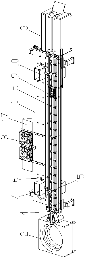
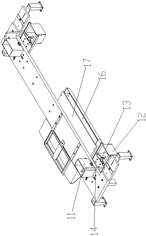
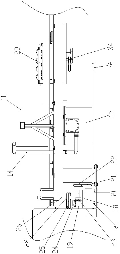
[0022] Such as Figure 1-4 As shown, the high-temperature inductance paint stripping and soldering all-in-one machine of the present invention includes a frame 1, a vibration plate 2 is arranged in front of the frame 1, a wave soldering machine 3 is arranged at the rear of the frame 1, and a driving motor is arranged on the frame 1 and two sets of transmission mechanisms, the two sets of transmission mechanisms are arranged side by side;

[0023] Every group of transmission mechanism comprises two turning wheels 4 and several supporting wheels 5, and the center line of turning wheels 4 and supporting wheels 5 is all vertically arranged, and wherein a turning wheel 4 is connected to the front end of frame 1 in rotation, and another turning wheel 4 Rotationally connected to the rear end of the frame 1, a conveyor belt 6 is connected between the two rotating wheels 4, the length direction of the conveyor belt 6 is consistent with the length direction of the frame 1, and several s...


PUM


Abstract

Disclosed is a high-temperature inductance paint-removing tin-soldering integrated machine. The integrated machine comprises a rack, the front portion of the rack is provided with a vibration plate, the rear portion of the rack is provided with a wave-peak tin-soldering machine, and the rack is provided with a driving motor and two conveying mechanisms arranged side by side in a left-right mode; each conveying mechanism comprises two rotating wheels and a plurality of supporting wheels, wherein the center lines of the rotating wheels and the center lines of the supporting wheels are all arranged vertically, one rotating wheel is rotatably connected to the front end of the rack, the other rotating wheel is rotatably connected to the rear end of the rack, a conveying belt is connected between the two rotating wheels, the length direction of the conveying belt is equal to that of the rack, and the supporting wheels are rotatably connected to the rack, all located between the left and right halves of the corresponding conveying belt and arranged side by side in the length direction of the corresponding conveying belt; thus, paint coats at the tail ends of copper wires of inductance coils are removed by means of assembly-line operation procedures, the tin-soldering operation is completed, and the production efficiency of the high-temperature inductance coils is improved.

Description

technical field [0001] The invention belongs to the technical field of inductance coil production, and in particular relates to a high-temperature inductance paint-removing and soldering integrated machine. Background technique [0002] With the advancement of science and technology and the improvement of people's living standards, the scale of the manufacturing industry is getting larger and larger, and the demand for inductance coils is also increasing; recently, the American research company MicroMarket Monitor released a "2014-2019 According to the report, the total value of the global inductor market in 2014 was 2.78 billion U.S. dollars, and it is expected to reach 3.75 billion U.S. dollars by 2019, with a compound annual growth rate of 6.2% from 2014 to 2019. It can be seen that the global demand for inductance coils is increasing day by day. [0003] The main steps in the production of inductance coils are to wind copper wires and solder on the skeleton, so that the...

Claims


Application Information

Patent Timeline
Patent Type & Authority Applications(China)
IPC IPC(8): H01F41/076
CPCH01F41/076
Inventor 张小明王龙飞郭天硕杨泽宇张浩王澳飞王敏杰司国臣
Owner HENAN POLYTECHNIC UNIV
Why Eureka
Try Eureka