
High-bearing flexible hinge guiding mechanism

A flexible hinge and guiding mechanism technology, applied in the directions of instruments and instrument parts, etc., can solve the problems such as deflection and displacement of the core motion platform, deformation of the flexible hinge array in the non-working direction, and the core motion platform cannot achieve the expected positioning accuracy, and achieves machining. The effect of low manufacturing cost, flexible processing form and wide application range

Active Publication Date: 2018-02-16
GUANGDONG UNIV OF TECH
View PDF9 Cites 5 Cited by
  • Summary
  • Abstract
  • Description
  • Claims
  • Application Information

AI Technical Summary

Problems solved by technology

[0008] In order to solve the technical problem that the flexible hinge array deforms in the non-working direction when the core motion platform is subjected to an excessively large torque from the driver, thereby causing the core motion platform to deflect and displace, resulting in the core motion platform being unable to achieve the expected positioning accuracy. The present invention provides a Large load flexible hinge guide mechanism

Method used


Image

  • High-bearing flexible hinge guiding mechanism
  • High-bearing flexible hinge guiding mechanism
  • High-bearing flexible hinge guiding mechanism

Examples


Embodiment 1

[0041] An embodiment of the large load-bearing flexible hinge guide mechanism proposed by the present invention 1 as Figure 5 shown. The main difference between the guide mechanism shown in Embodiment 1 and the existing flexible hinge guide mechanism is the addition of a sub-flexible hinge (401) for carrying large loads and resisting deformation in the non-working direction. The working principle of embodiment 1 guiding mechanism is: as Figure 6 and Figure 7 As shown, the core motion platform (3) is connected to the rigid support platform (1) through the main flexible hinge group (2) and the secondary flexible hinge group (401) respectively. The flexible hinges in the main flexible hinge group (2) and the secondary flexible hinge group (401) are processed and manufactured in one piece with the rigid support platform (1), and the secondary flexible hinge group (401) is manufactured through a rigid connection part ( 402) Connect with the core motion platform (3). The main...

Embodiment 2

[0045] An embodiment of the flexible hinge guiding mechanism proposed by the present invention 2 is as Figure 10 to Figure 12 shown. The main difference between the guiding mechanism of embodiment 2 and the guiding mechanism of embodiment 1 is that the sub-flexible hinge group (401) of embodiment 1 is manufactured by integral processing with the rigid support platform, and the sub-flexible hinge group described in embodiment 2 Groups are manufactured by component assembly.

[0046] Such as Figure 11 and Figure 12 As shown, the sub-flexible hinge group includes spring leaf (401a), bolt group B (405), bolt group C (406), connection block A (407), connection block B (408) and so on. Wherein, the spring piece (401a) is rigidly connected with the rigid support platform (1) through the bolt group B (405), and the core motion platform (3) is connected through the connecting block B (408) and the connecting block A (407) Parts such as bolt group C (406) and the middle part of t...


PUM


Abstract

The invention discloses a high-bearing flexible hinge guiding mechanism. The high-bearing flexible hinge guiding mechanism comprises a core moving platform (3), a rigid supporting platform (1), a mainflexible hinge assembly (2) and a secondary flexible hinge assembly (401), wherein the main flexible hinge assembly (2) and the secondary flexible hinge assembly (401) are arranged in different directions. Through cooperation of the main flexible hinge assembly (2) and the secondary flexible hinge assembly (401), the technical problem that when the core moving platform is subjected to too large applied moment of an actuator, the core moving platform can not achieve the expected positioning precision is effectively prevented.

Description

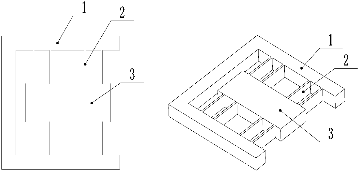
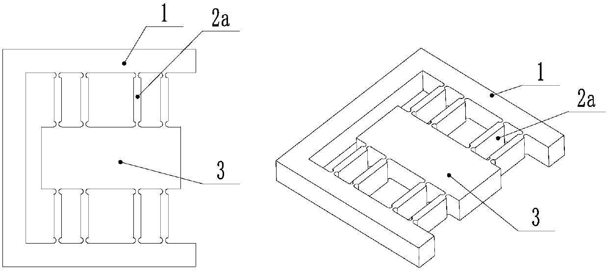
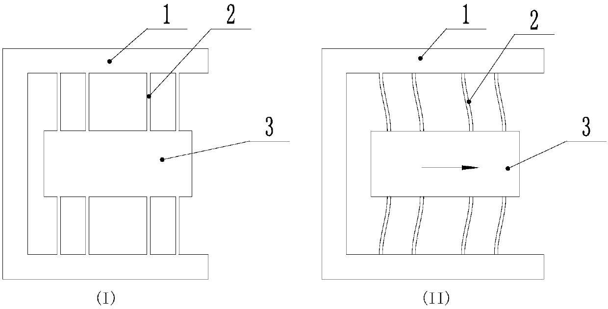
technical field [0001] The invention relates to the technical field of precision motion platforms, and more specifically, to a large-load flexible hinge guide mechanism. Background technique [0002] Flexible hinges are widely used in the design of precision motion platforms due to their frictionless and lubrication-free properties. In the design of precision motion platforms, flexible hinges are mainly used in the design of guiding mechanisms. [0003] figure 1 It is an existing typical flexible hinge guide mechanism. Such as figure 1 As shown, the core motion platform 3 is connected to the rigid support platform 1 through the flexible hinge array 2 . figure 1 In the shown flexible hinge array 2, a straight beam type flexible hinge is used. In particular, the flexible hinge array 2 can also be made of figure 2 The flexible hinge array 2a formed by the notched flexible hinge shown. [0004] figure 1 The working principle of the flexible hinge guide structure shown is...

Claims


Application Information

Patent Timeline
Patent Type & Authority Applications(China)
IPC IPC(8): G12B5/00G12B3/00
CPCG12B3/00G12B5/00
Inventor 杨志军李乾白有盾陈新陈桪何耀滨孙晗黄观新吴栢生
Owner GUANGDONG UNIV OF TECH
Learn More