
Multifunctional drying device for textile fabric

A textile fabric and drying device technology, applied in the direction of drying, drying machine, drying gas arrangement, etc., can solve the problems of affecting the drying effect of textile fabrics, increasing production costs, unfavorable environmental protection and saving, etc., and achieves simple structure, effective Convenience in drying, convenient and ingenious effect

Inactive Publication Date: 2018-02-16
湖州佳伟纺织品有限公司
View PDF0 Cites 5 Cited by
  • Summary
  • Abstract
  • Description
  • Claims
  • Application Information

AI Technical Summary

Problems solved by technology

[0002] In the production of textile fabrics, the dryer is one of the indispensable production equipment. The quality of the dryer will directly affect the quality of the textile fabric. The current dryer mainly includes a drying box and a drying box. The heating device, the heating device generates heat so that the temperature in the drying box reaches the specification requirements and then dries the cloth in the drying box. During long-term use, it is found that because the textile fabric walks horizontally or in a U-shaped line in the drying box , and the position of the heating device is fixed, so it is difficult to make the distance between each part of the textile fabric and the heating device equal in the above method, so the phenomenon of uneven heating will occur; when drying, there will be more water in the drying box Steam affects the drying effect of textile fabrics, and the hot air containing moisture is directly discharged, which increases production costs, wastes a lot of energy, and causes thermal pollution, which is not conducive to environmental protection and saving

Method used


Image

  • Multifunctional drying device for textile fabric
  • Multifunctional drying device for textile fabric
  • Multifunctional drying device for textile fabric

Examples


Embodiment Construction

[0020] The following will clearly and completely describe the technical solutions in the embodiments of the present invention with reference to the accompanying drawings in the embodiments of the present invention. Obviously, the described embodiments are only some, not all, embodiments of the present invention.

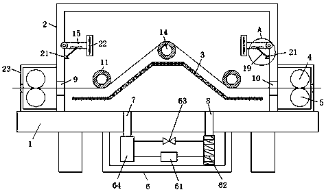
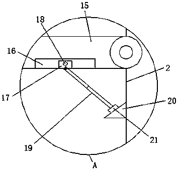
[0021] refer to Figure 1-3 , a multifunctional drying device for textile fabrics, comprising a workbench 1, the upper end of the workbench 1 is fixedly connected to a body shell 2, and the outer wall of the body shell 2 is symmetrically provided with a material inlet 9 and a material outlet 10, and the inlet One side of the outer wall of the feed port 9 and the discharge port 10 is fixedly connected with a mounting frame 23, the inner wall of the mounting frame 23 is equipped with an upper traction roller 4 and a lower traction roller 5, and the inner wall of the body shell 2 is evenly distributed with several rotating rollers 11, and the two sides of the outer wall...


PUM


Abstract

The invention discloses a multifunctional drying device for textile fabric. The multifunctional drying device for the textile fabric comprises a workbench. The upper end of the workbench is fixedly connected with a machine body shell. An upper traction roller and a lower traction roller are installed on the inner wall of a mounting frame. A plurality of rotating rollers are evenly distributed on the inner wall of the machine body shell in a staggered mode. The two sides of the inner wall of the machine body shell are symmetrically and rotationally connected with motion bars, and a fan is arranged at the end, away from the machine body shell, of each motion bar. Each inclined block is fixed to one side of the inner wall of the machine body shell. The textile fabric is arranged inside the machine body shell. The textile fabric enters the machine body shell from a feeding inlet, sequentially passes through the multiple rotating rollers and is discharged from a discharging outlet. A dryingbox is installed at the bottom of the workbench. The multifunctional drying device for the textile fabric is simple in structure and easy to operate, achieves circular drying of the textile fabric, improves drying efficiency, meanwhile, does not damage the textile fabric, and improves the quality of products.

Description

technical field [0001] The invention relates to the technical field of textiles, in particular to a multifunctional drying device for textile fabrics. Background technique [0002] In the production of textile fabrics, the dryer is one of the indispensable production equipment. The quality of the dryer will directly affect the quality of the textile fabric. The current dryer mainly includes a drying box and a drying box. The heating device, the heating device generates heat so that the temperature in the drying box reaches the specification requirements and then dries the cloth in the drying box. During long-term use, it is found that because the textile fabric walks horizontally or in a U-shaped line in the drying box , and the position of the heating device is fixed, so it is difficult to make the distance between each part of the textile fabric and the heating device equal in the above method, so the phenomenon of uneven heating will occur; when drying, there will be more...

Claims


Application Information

Patent Timeline
Patent Type & Authority Applications(China)
IPC IPC(8): F26B13/08F26B13/10F26B13/12F26B21/04
CPCF26B13/08F26B13/108F26B13/12F26B21/04
Inventor 朱振华
Owner 湖州佳伟纺织品有限公司
Learn More