
An iterative demodulation and decoding method for wireless optical communication multi-level coding modulation system

A wireless optical communication, coding and modulation technology, which is applied in the field of demodulation and decoding, can solve the problems of reduced error performance and difficulty in system communication, and achieves the effect of saving iteration time overhead and excellent error performance.

Active Publication Date: 2020-09-04
NAVAL AVIATION UNIV
View PDF5 Cites 0 Cited by
  • Summary
  • Abstract
  • Description
  • Claims
  • Application Information

AI Technical Summary

Problems solved by technology

Error propagation will lead to a serious drop in the bit error performance of system communication. The current approach is to analyze the sub-channel capacity corresponding to the component codes at all levels, and then configure channel codes with different error correction capabilities on this basis.
This method needs to accurately estimate the channel state information of each sub-channel, which is obviously difficult to achieve in the actual communication process

Method used


Image

  • An iterative demodulation and decoding method for wireless optical communication multi-level coding modulation system
  • An iterative demodulation and decoding method for wireless optical communication multi-level coding modulation system
  • An iterative demodulation and decoding method for wireless optical communication multi-level coding modulation system

Examples


Embodiment 1

[0025] In this embodiment, the wireless optical communication system adopts third-order PPM modulation, correspondingly requires three-level channel coding, and the three-level component codes are respectively configured as BCH (127, 113) code, BCH (127, 99) code and BCH (127, 85) code, the PPM modulation mapping method is shown in Table 1, wherein, (a 1 ,a 2 ,a 3 ) represents a modulation group, m i (i=0,1,...,7) represents the position of the modulated optical pulse on the time slot of the PPM symbol, and the PPM modulation represents information through the difference in the position of the time slot within the symbol where the optical pulse is located.

[0026] Table 1 PPM mapping method

[0027]

[0028] First, three sets of source sequences are generated at the sending end, and these three sets of source data are respectively sent to a three-stage channel encoder for encoding, and then modulated into an optical PPM signal for transmission. After channel transmissio...

Embodiment 2

[0063] In this embodiment, the wireless optical communication system still adopts third-order PPM modulation, and the corresponding three-level component codes are configured in the order of BCH (127, 85) code, BCH (127, 99) code and BCH (127, 113) code, In this configuration, multi-stage demodulation and decoding have minimal error propagation. At this time, the bit error performance curves of using iteration (ITE=1, 2, 3) and non-iteration (ITE=0, using multi-stage demodulation and decoding method) are as follows Figure 5 shown. It can be seen from the figure that the four curves almost overlap together, that is, the present invention cannot obtain gain improvement at this time, but it will not cause system performance degradation either.


PUM


Abstract

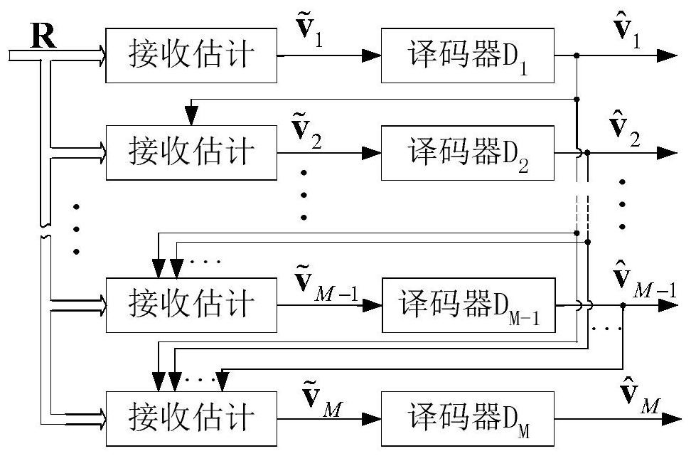
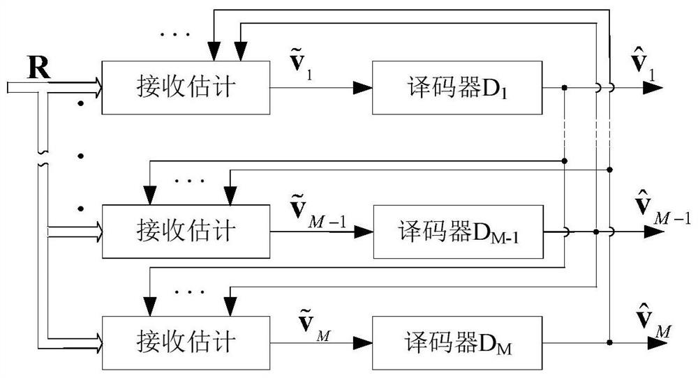
The invention discloses an iterative demodulation and decoding method for wireless optical communication multi-level coding modulation. The method comprises the following steps: construction of a unity feedback structure extending from decoding to receiving estimation, iteration initial value acquisition, iteration updating and iteration stopping on the receiving estimation v-tilde and decoding output v-triangle through the unity feedback structure, etc. In a multi-level coding modulation wireless optical communication system, the method achieves better error performance than a multi-stage demodulation and decoding method when error propagation is caused by improper configuration of component codes, and the error performance of the method is equal to that of the multi-stage demodulation and decoding method when the error propagation is not caused by the configuration of the component codes.

Description

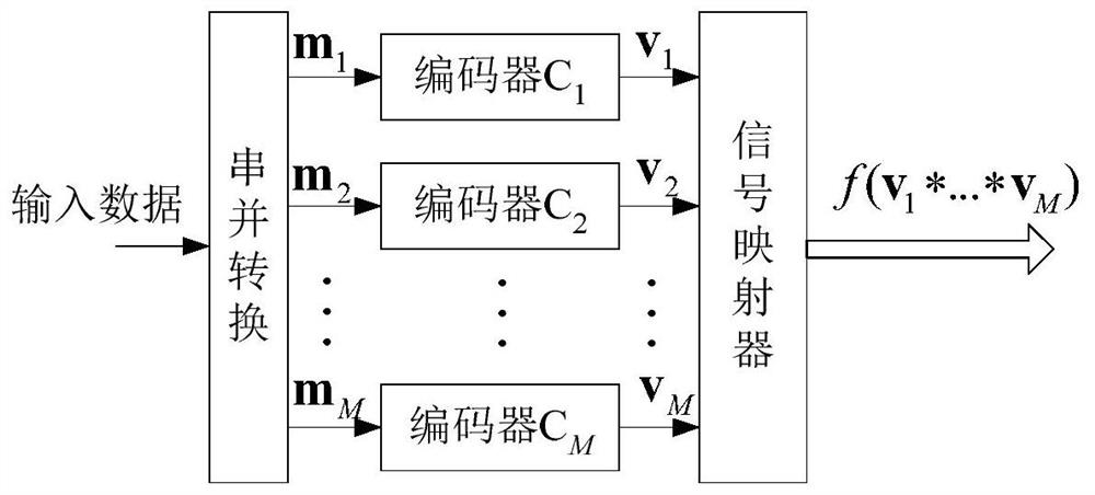
technical field [0001] The invention relates to a demodulation and decoding method of a wireless optical communication multi-level coding and modulation system, in particular to an iterative demodulation and decoding method of multi-level coding and modulation and its realization. Background technique [0002] The channel condition of the wireless communication system is generally bad, and using channel error correction coding is one of the common methods to improve communication reliability. Generally speaking, a good coding and modulation design is to construct long codewords and realize random coding, and to approximate or realize maximum likelihood demodulation and decoding at the receiving end. However, the algorithm of maximum likelihood decoding of long codewords is often very complicated and difficult to realize. Multi-level coding and modulation technology can construct multiple short code words into one long code word, and realize random coding through simple inte...

Claims


Application Information

Patent Timeline
Patent Type & Authority Patents(China)
IPC IPC(8): H04L1/00
CPCH04L1/005H04L1/0051H04L1/0057H04L1/0065
Inventor 胡昊王红星张骁毛忠阳刘敏杨凡刘锡国
Owner NAVAL AVIATION UNIV
Learn More