A Rocker Mechanism Used to Control Camera Shooting Angle

A technology of shooting angle and rocker mechanism, which is applied in the mechanical field, can solve problems such as joint error accumulation, poor dynamic performance of the mechanism, and difficulty in ensuring high accuracy, so as to reduce the moment of inertia and vibration coupling, improve the bearing capacity, and reduce the manufacturing cost. low effect

Active Publication Date: 2019-01-29
济宁高新科达科技项目服务有限公司
View PDF6 Cites 0 Cited by
  • Summary
  • Abstract
  • Description
  • Claims
  • Application Information

AI Technical Summary

Problems solved by technology

However, due to the limitation of its own structure, the traditional rocker arm mechanism will cause problems such as heavy arm weight, poor rigidity, large inertia, joint error accumulation, and poor dynamic performance of the mechanism. Due to the light load of the mechanical arm, it is difficult to install the volume , heavy working device, high accuracy is difficult to guarantee

Method used


Image

  • A Rocker Mechanism Used to Control Camera Shooting Angle
  • A Rocker Mechanism Used to Control Camera Shooting Angle
  • A Rocker Mechanism Used to Control Camera Shooting Angle

Examples


Embodiment 1

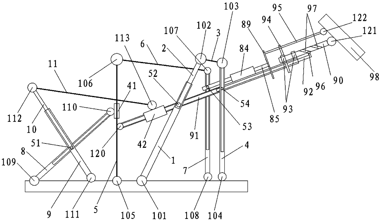
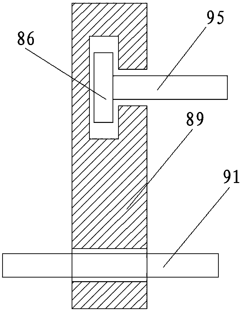
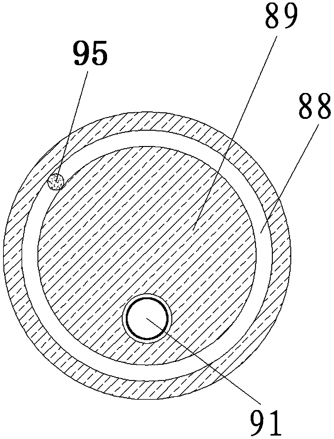
[0032] The rocker mechanism used to control the shooting angle of the camera, including pole one 1, pole two 2, pole three 3, pole four 4, pole five 5, pole six 6, pole seven 7, pole eight 8, pole nine 9, pole ten 10. Rod eleven 11, first cylindrical pin 51, second cylindrical pin 52, third cylindrical pin 53, fourth cylindrical pin 54, slider 86, ring rail plate 89, rotating shaft 90, boom 91, stick 92 , bearing 93, inner limit ring 94a, outer limit ring 94b, force rod 95, sphere 96, cylindrical helical groove 97, actuator 98 and frame 99,

[0033] One end of the rod one 1 is connected to the frame 99 through the rotation pair one 101, the other end of the rod one 1 is connected with one end of the rod two 2 through the axial movement pair to form a telescopic rod, and the other end of the rod two 2 is connected to the rod three 3 through the rotation pair two 102 One end is connected, and the other end of bar three 3 is connected with one end of bar four 4 by rotating pair t...


PUM


Abstract

The rocker mechanism is used to control the shooting angle of the camera. One end of rod one is connected to the frame and the other end is connected to one end of rod two. The other end of rod two is connected to one end of rod three, and the other end of rod three is connected to one end of rod four. , the other end of rod four is connected to the frame, one end of rod eight is connected to the frame, the other end is connected to the first sliding sleeve, the first sliding sleeve is set on rod six, one end of rod nine is connected to the frame and the other end is connected to the frame One end is connected to one end of rod ten, the other end of rod ten is connected to one end of rod eleven, the other end of rod eleven is connected to the second sliding sleeve, the second sliding sleeve is set on the moving arm, and one end of the rotating shaft is fixed to the inner ring of the bearing For installation, the outer ring of the bearing is fixed on the boom, and the other end of the rotating shaft is connected to the actuator; Installed in the helical groove of the cylinder, one end of the force application rod is connected to the actuator, the other end of the force application rod is connected to the slider, and the slider is embedded in the rail groove of the ring rail plate.

Description

technical field [0001] The invention relates to the mechanical field, in particular to a rocker mechanism for controlling the shooting angle of a camera. Background technique [0002] In the era of ever-changing TV technology, the rocker camera technology has played a role that cannot be ignored in variety shows, sports, talk programs and other programs. It greatly enriches the lens language of TV programs, increases the dynamics and diversification of the lens images, adds majestic momentum and a sense of depth and space to the lens images, and makes the audience feel immersive; and, because the rocker camera With its unique long arm advantage, it can often capture shots that other cameras cannot capture. However, due to the limitation of its own structure, the traditional rocker arm mechanism will cause problems such as heavy arm weight, poor rigidity, large inertia, joint error accumulation, and poor dynamic performance of the mechanism. Due to the light load of the mech...

Claims


Application Information

Patent Timeline
Patent Type & Authority Patents(China)
IPC IPC(8): F16M11/04F16M11/14F16M11/18F16M11/26F16M11/42G03B17/56
CPCG03B17/56F16M11/043F16M11/14F16M11/18F16M11/26F16M11/42
Inventor 不公告发明人
Owner 济宁高新科达科技项目服务有限公司
Why Eureka
Try Eureka