Electric-magnetic door lock control device

A technology for electromagnetic door locks and control devices, which can be used in building locks, locks controlled by non-mechanical transmission, buildings, etc., and can solve the problem of low safety of electromagnetic door locks

Active Publication Date: 2018-02-09
SHENZHEN JPT OPTO ELECTRONICS CO LTD
View PDF8 Cites 2 Cited by
  • Summary
  • Abstract
  • Description
  • Claims
  • Application Information

AI Technical Summary

Problems solved by technology

[0004] Based on this, it is necessary to provide an electromagnetic door lock control device that can improve safety for the problem of low security of existing electromagnetic door locks.

Method used


Image

  • Electric-magnetic door lock control device
  • Electric-magnetic door lock control device
  • Electric-magnetic door lock control device

Examples


Embodiment Construction

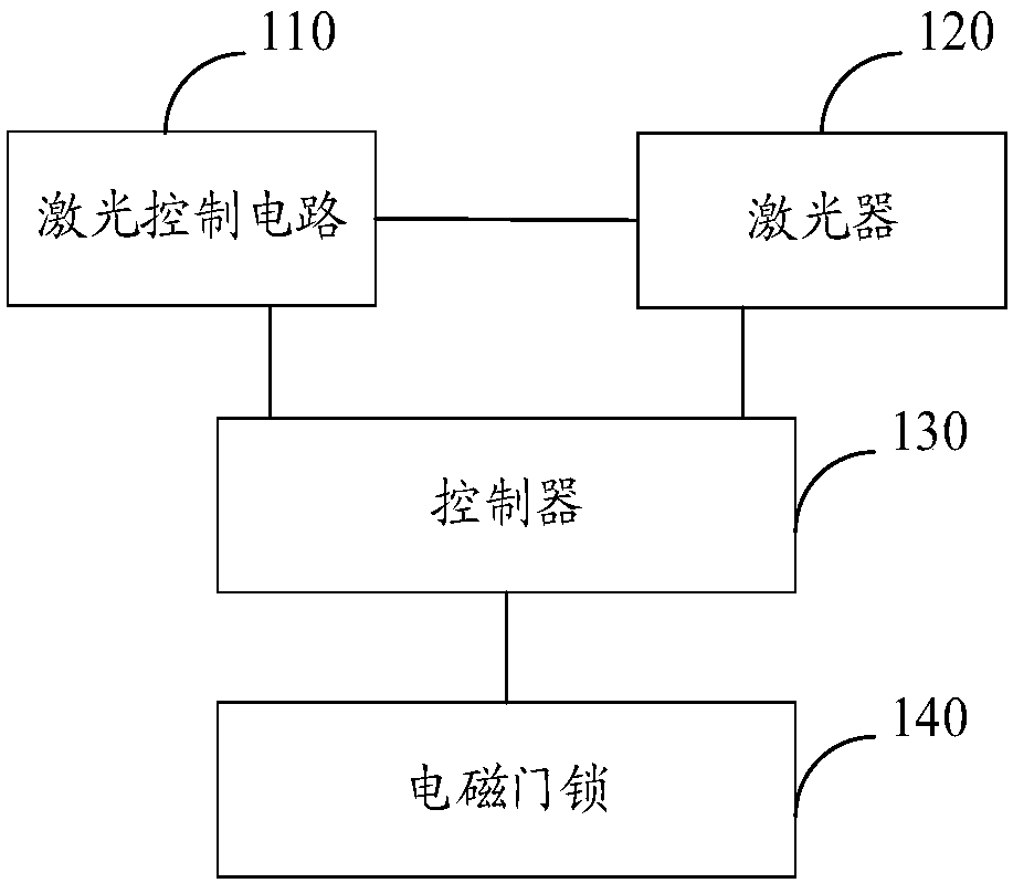
[0023] see figure 1 , providing an embodiment of an electromagnetic door lock control device, including a laser control circuit 110 , a laser 120 and a controller 130 . Wherein, the controller 130 is respectively connected to the laser control circuit 110 , the laser 120 and the electromagnetic door lock 140 , and the laser control circuit 110 is connected to the laser 120 .

[0024] After the laser control circuit 110 controls the power-on of the laser 120, the laser control circuit 110 sends the laser power-on state signal to the controller 130, and the electromagnetic door lock 140 sends the closed state signal to the controller 130 when detecting that the door is in the closed state, After receiving the laser power-on state signal and the laser off state signal, the controller 130 sends a laser power-on signal to the laser 120 to control the laser 120 to emit laser light and output a control signal to control the electromagnetic door lock 140 to enter the locked state.

...


PUM


Abstract

The invention discloses an electric-magnetic door lock control device which comprises a laser control circuit, a laser and a controller. The controller is connected with the laser control circuit, thelaser and an electric-magnetic door lock; and the laser control circuit is connected with the laser. After the laser control circuit controls the laser to power on, the laser control circuit sends alaser power-on state signal to the controller; when the electric-magnetic door lock detects that a door is in a close state, the electric-magnetic door lock sends a close state signal to the controller; and after the controller receives the laser power-on state signal and the close state signal, the controller sends a laser starting signal to the laser so as to control the laser to emit laser light, and outputs a control signal to control the electric-magnetic door lock to enter a locking state. The controller controls the laser to emit the laser light and controls the electric-magnetic door lock to enter the locking state only if the controller receives the laser power-on state signal and the close state signal, so that the laser is safely controlled, other people are prevented from beinginjured accidently, and the electric-magnetic door lock is accurately controlled.

Description

technical field [0001] The invention relates to the technical field of electronic devices, in particular to an electromagnetic door lock control device. Background technique [0002] At present, in order to improve indoor safety, more and more people prefer to install electromagnetic door locks with lasers. Electromagnetic door locks with lasers emit laser light through lasers to ensure indoor safety. [0003] However, the existing laser for electromagnetic door locks with lasers is prone to accidentally opening the door when the laser emits light, which may easily cause accidental injury. The low safety level of the laser leads to low safety of the electromagnetic door lock and high risk of use. Contents of the invention [0004] Based on this, it is necessary to provide an electromagnetic door lock control device capable of improving safety for the problem of low security of the existing electromagnetic door lock. [0005] An electromagnetic door lock control device, ch...

Claims


Application Information

Patent Timeline
IPC IPC(8): E05B47/00E05B17/22
CPCE05B17/22E05B47/00E05B2047/0068E05B2047/0048
Inventor 李刚金
Owner SHENZHEN JPT OPTO ELECTRONICS CO LTD
Why Eureka
Try Eureka