
Follow-up external rearview mirror for vehicle

A technology for exterior rearview mirrors and rearview mirrors, which is applied in the field of automobile rearview mirrors, and can solve problems such as affecting the driver's distance judgment, small curvature radius, and ineffective reduction of blind spots.

Inactive Publication Date: 2018-02-06
NORTHEAST FORESTRY UNIVERSITY
View PDF0 Cites 3 Cited by
  • Summary
  • Abstract
  • Description
  • Claims
  • Application Information

AI Technical Summary

Problems solved by technology

Due to the existence of the blind spot in the car rearview mirror, it is difficult for the driver in the car to observe other vehicles close to the rear door without looking back. When performing merge or steering operations, there is a great potential safety hazard, which is likely to cause traffic accidents. ACCIDENT
[0003] At present, in order to reduce the blind area of ​​the driver's vision, some methods have been adopted. Among them, the installation of double-curvature rearview mirrors can reduce the blind area, but the outer curvature radius of the double-curvature rearview mirror is small, causing visual field distortion and affecting the judgment of the driver's vehicle distance. ;The blind spot mirror is installed to occupy the original rearview mirror, and the effect of reducing the blind spot is not obvious, which affects the appearance; the use of camera imaging is high in cost and low in reliability. In extreme weather conditions such as failure or heavy rain, the driver may be completely lost. vehicle rear view

Method used


Image

  • Follow-up external rearview mirror for vehicle
  • Follow-up external rearview mirror for vehicle
  • Follow-up external rearview mirror for vehicle

Examples


Embodiment Construction

[0030] Exemplary embodiments of the present invention will be described below with reference to the accompanying drawings.

[0031] An embodiment of the present invention provides a follow-up exterior rearview mirror for a vehicle.

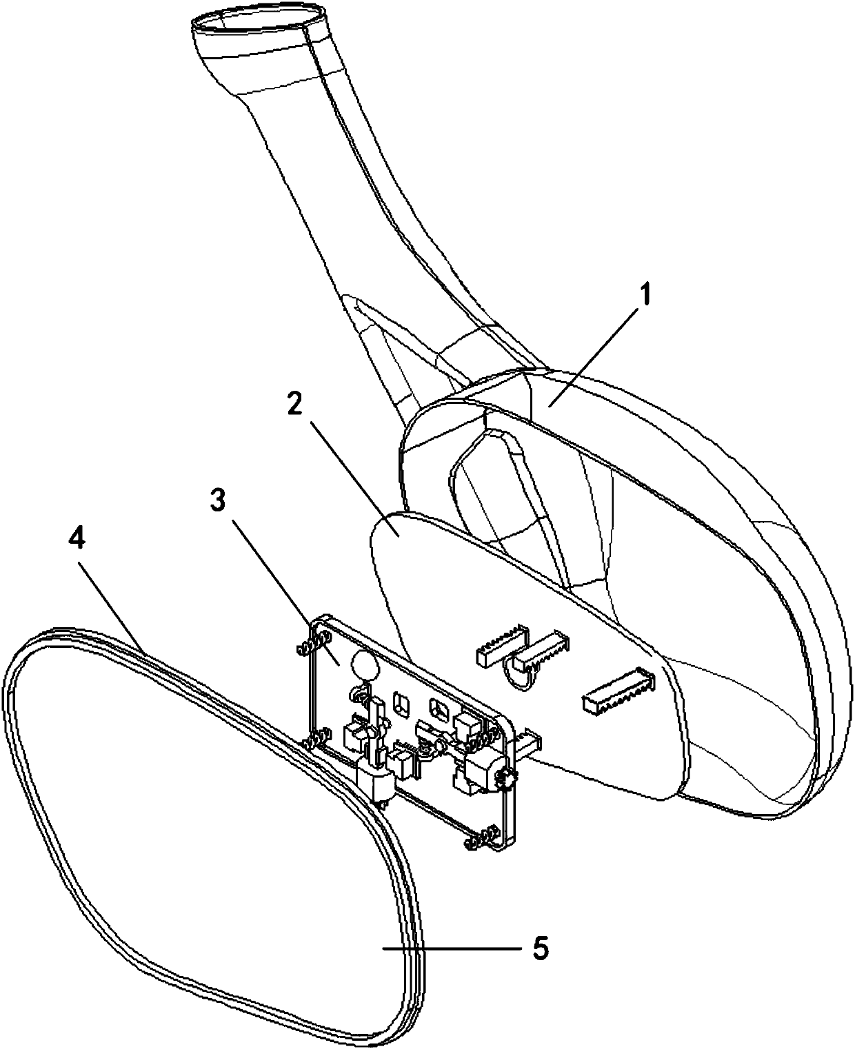
[0032] Such as figure 1 As shown, the follow-up exterior rearview mirror includes an exterior rearview mirror housing 1 , a rearview mirror frame 2 , a motor seat 3 , a lens seat 4 and a lens 5 . The outer rearview mirror housing 1 is rigidly connected with the rearview mirror frame 2; the outer rearview mirror frame 2 is connected with the motor seat 3; the motor seat 3 is connected with the lens seat 4;

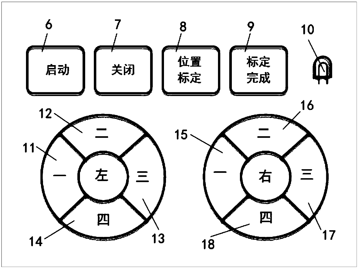
[0033] Such as figure 2As shown, the control panel includes four buttons, two groups of function keys and a status indicator. The start button 6 is used to start or restart the follow-up exterior rearview mirror system. The off button 7 turns off the follow-up exterior rearview mirror system. Position calibration key 8 is used for positio...


PUM


Abstract

The invention provides a follow-up exterior rearview mirror for a vehicle. The follow-up exterior rearview mirror includes a control panel, a central processing unit, an exterior rearview mirror housing, a rearview mirror frame, a motor seat, a lens seat, lenses and connectors. The control panel controls the gear position of the motor on the connecting rod through the buttons to realize the two functions of system initial position calibration and normal operation: when the initial position is calibrated, two sets of buttons are used to control the forward and reverse rotation of the motors in the left and right rearview mirrors, and adjust the proper position of the rearview mirror; When working, when the vehicle is running, the central processing unit receives the signals of vehicle speed and steering wheel angle, controls the forward and reverse rotation of the motor, and adjusts the angle of the lens seat in real time to realize the follow-up function of the rearview mirror. The design of the locking structure and spring structure ensures that in the event of system failure, the rearview mirror is still in a proper position, and the driver still has a normal rear view of the car, which improves the reliability of the system. The above-mentioned technical route of the present invention can reduce the blind area of ​​the vehicle's side and rear vision when the driver merges and turns, and improves driving safety.

Description

technical field [0001] The invention relates to automobile rearview mirror technology, in particular to a follow-up exterior rearview mirror system for vehicles. Background technique [0002] As a part of the car, the rearview mirror plays an important role in the situations of merging, overtaking and reversing. Due to the existence of the blind spot in the car rearview mirror, it is difficult for the driver in the car to observe other vehicles close to the rear door without looking back. When performing merge or steering operations, there is a great potential safety hazard, which is likely to cause traffic accidents. ACCIDENT. [0003] At present, in order to reduce the blind area of ​​the driver's vision, some methods have been adopted. Among them, the installation of double-curvature rearview mirrors can reduce the blind area, but the outer curvature radius of the double-curvature rearview mirror is small, causing visual field distortion and affecting the judgment of the...

Claims


Application Information

Patent Timeline
IPC IPC(8): B60R1/072
CPCB60R1/072
Inventor 唐文秀奚文龙李志鹏常子凡
Owner NORTHEAST FORESTRY UNIVERSITY
Learn More