
Power system control method based on event-triggered dynamic triggering mechanism

An event-triggered, power system technology, applied in system integration technology, information technology support systems, electrical components, etc., can solve problems such as many triggering times, complex event-triggered controller design, and complex matrix.

Active Publication Date: 2018-02-02
ANHUI UNIVERSITY
View PDF6 Cites 17 Cited by
  • Summary
  • Abstract
  • Description
  • Claims
  • Application Information

AI Technical Summary

Problems solved by technology

[0007] 1) The trigger conditions are slightly optimized, but the controllability is not high, and the number of triggers is large;
[0008] 2) There is no proof of the stability of event triggering;
[0009] 3) The matrix is ​​relatively complex, and the calculation amount is relatively large for solving the controller
[0014] 1) The design of this control method and event-triggered controller is more complicated;
[0015] 2) The structure of the dynamic model is relatively complex
[0016] 3) There is no proof of stability for event triggering

Method used


Image

  • Power system control method based on event-triggered dynamic triggering mechanism
  • Power system control method based on event-triggered dynamic triggering mechanism
  • Power system control method based on event-triggered dynamic triggering mechanism

Examples


Embodiment Construction

[0092] The embodiments of the present invention are described in detail below. This embodiment is implemented on the premise of the technical solution of the present invention, and detailed implementation methods and specific operating procedures are provided, but the protection scope of the present invention is not limited to the following implementation example.

[0093] like figure 1 , the present invention considers the linear control model of single-machine power system.

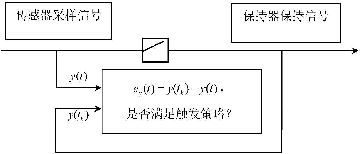
[0094] The power system structure is basically composed of generators, PMU (power system synchrophasor measurement unit), sensors, event generators, keepers, controllers and actuators. The PMU is connected to the generator for dynamic real-time monitoring ; Transmit the output y(t) of the PMU terminal to the sensor, the sensor is used to receive and store the signal; the event trigger control is introduced behind the sensor, and the control process is operated through the event generator; the holder is...


PUM


Abstract

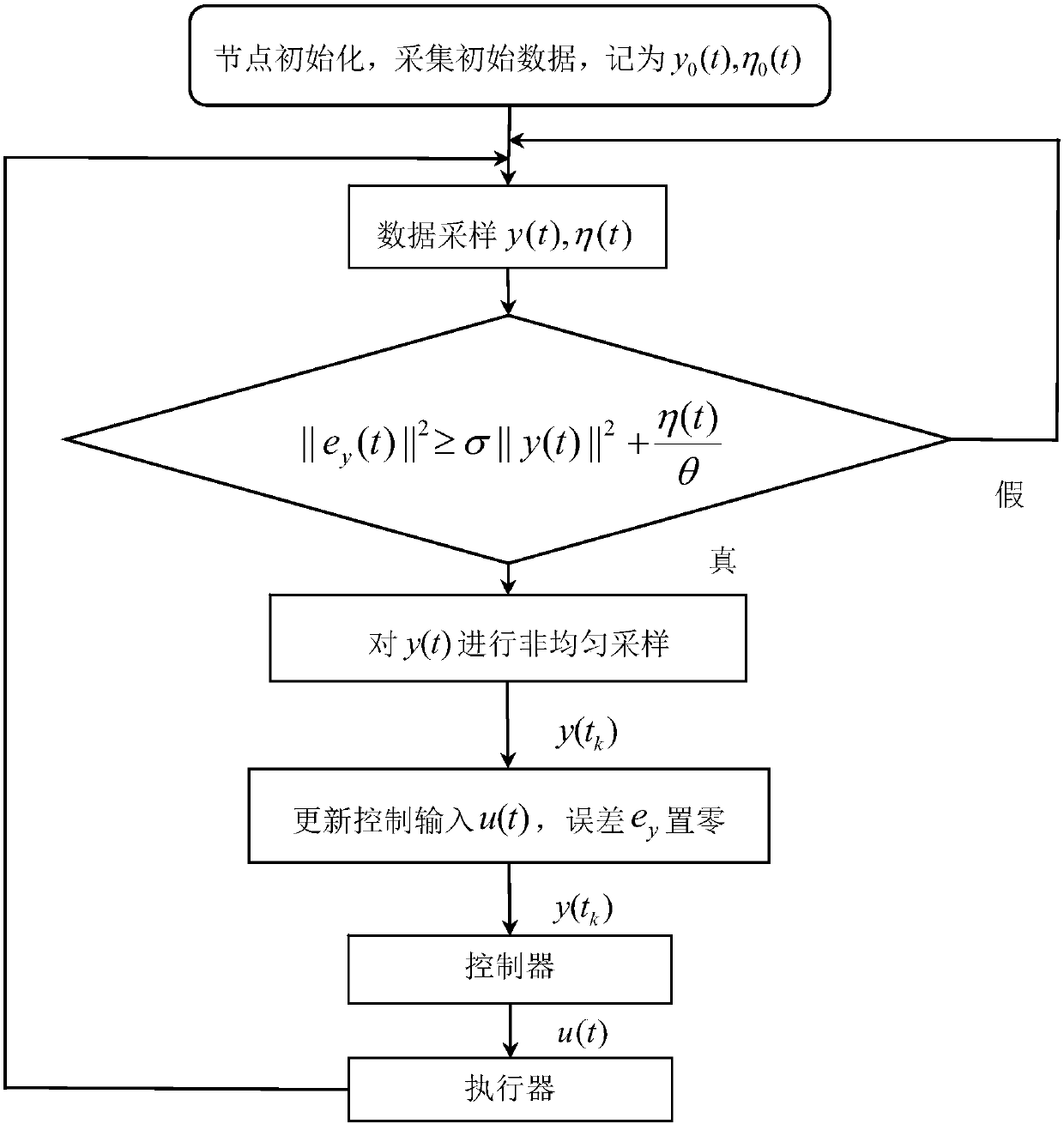
The invention discloses a power system control method based on the event-triggered dynamic triggering mechanism. a PMU is connected to a generator for dynamic and real-time monitoring; an output y(t)of the PMU is transmitted to a sensor, wherein the sensor is used for receiving and storing signals; an event generator is introduced after the sensor and a control process is operated by the event generator; a retainer is connected after the event generator and is used for keeping an output y(tk) of the event generator constant in [tk,tk+1] during the process of event triggering sampling; if a dynamic triggering strategy is satisfied, then triggering, i.e., non-uniform sampling, is carried out by the event generator; an output y(tk) is obtained by updating data; then an input u(t) of a controller is updated; finally, the updated input u(t) is transmitted to an executor and returned to the generator to continue updating the output y(t); the above steps are cycled. Compared with the prior art, the invention has the following advantages: the dynamic triggering mechanism relates not only to the current output and error, but also to the previous one; adding internal dynamic variables makesit easier to control and adjust the system's event triggering strategy.

Description

technical field [0001] The invention relates to a power system control method, in particular to a power system control method based on an event-triggered dynamic trigger mechanism. Background technique [0002] The interconnection of large power grids can improve the economy of system operation, and has become an inevitable choice for a conservation-minded society, and it also puts forward new requirements for various control systems in power grid operation. Running all kinds of control information and its dynamic operation information in the power system on the same dedicated network platform for power information will become the main direction of future intelligent control grid construction. In the power system, how to design an effective control strategy to meet the real-time requirements as much as possible? At present, the phasor measurement unit in the power system basically collects and sends signals at equal intervals. However, from the perspective of network resou...

Claims


Application Information

Patent Timeline
IPC IPC(8): H02J3/00H02J3/46
CPCH02J3/00H02J3/46H02J2203/20Y02E40/70Y02E60/00Y04S10/00Y04S10/22
Inventor 樊渊张成笑
Owner ANHUI UNIVERSITY
Learn More