
Curved-surface display panel and curved-surface display device

A curved surface display and panel technology, which is applied in the direction of identification devices, nonlinear optics, instruments, etc., can solve problems affecting the display quality of the display panel, uneven thickness of liquid crystal cells, and differences in supporting force

Active Publication Date: 2018-02-02
BOE TECH GRP CO LTD +1
View PDF18 Cites 12 Cited by
  • Summary
  • Abstract
  • Description
  • Claims
  • Application Information

AI Technical Summary

Problems solved by technology

[0005] Embodiments of the present invention provide a curved display panel and a curved display device, which can solve the problem in the prior art that the spacers made on the array substrate or the box substrate of the curved display panel have a smaller area at the top than the area at the bottom. There is a difference in the supporting force between the array substrate and the cell substrate, resulting in uneven thickness of the liquid crystal cell and affecting the display quality of the display panel

Method used


Image

  • Curved-surface display panel and curved-surface display device
  • Curved-surface display panel and curved-surface display device
  • Curved-surface display panel and curved-surface display device

Examples


Embodiment Construction

[0026] The following will clearly and completely describe the technical solutions in the embodiments of the present invention with reference to the accompanying drawings in the embodiments of the present invention. Obviously, the described embodiments are only some, not all, embodiments of the present invention. Based on the embodiments of the present invention, all other embodiments obtained by persons of ordinary skill in the art without making creative efforts belong to the protection scope of the present invention.

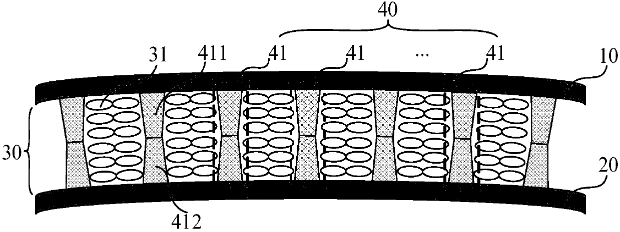
[0027] An embodiment of the present invention provides a curved display panel, such as figure 1 As shown, it includes a first substrate 10 and a second substrate 20 facing each other, a liquid crystal layer 31 disposed in a gap 30 between the first substrate 10 and the second substrate 20, and a liquid crystal layer 31 in the gap 30 between the first substrate 10 and the second substrate 20. A spacer layer 40 for supporting the first substrate 10 and the secon...


PUM


Abstract

The embodiment of the invention provides a curved-surface display panel and a curved-surface display device, and relates to the technical field of displaying. In the prior art, when an array substrateof the curved-surface display panel or a spacer on a box alignment substrate is prepared, the area of the top is smaller than the area of the bottom, so that the supporting force applied by the spacer to the array substrate and the support force applied by the spacer to the box alignment substrate are different, the thickness of a liquid crystal box is uneven, the image display quality of the display panel is affected, and such problem is solved by the curved-surface display panel and the curved-surface display device. The curved-surface display panel includes a first substrate, a second substrate and a liquid crystal layer, wherein the first substrate and the second substrate are subjected to box alignment mutually, and the liquid crystal layer is arranged in a gap between the first substrate and the second substrate, and a spacer layer is arranged in the first substrate and the second substrate and used for supporting the first substrate and the second substrate so as to form a gap.The spacer layer includes several spacer sets, and the spacer set includes a first spacer and a second spacer, the first spacer is arranged on the first substrate and the second spacer is arranged onthe second substrate, and the supporting area, on the first substrate, of the spacer set is equal to the supporting area, on the second substrate, of the spacer set.

Description

technical field [0001] The invention relates to the field of display technology, in particular to a curved display panel and a curved display device. Background technique [0002] The liquid crystal display panel includes an array substrate, a cell-mounted substrate, a liquid crystal layer and a spacer (Photo Spacer, PS for short) located between the array substrate and the cell-mounted substrate. The spacers mainly play a supporting role to support the gap between the array substrate and the counter substrate, and prevent the liquid crystal molecules from being subjected to excessive pressure between the array substrate and the counter substrate. [0003] With the increasing maturity of liquid crystal display technology, the screen can be properly curved to adapt to the curvature of ergonomics, and the curved display panel that makes the distance between the human eye line of sight and each point on the screen close to obtain better visual effects has become a further devel...

Claims


Application Information

Patent Timeline
IPC IPC(8): G02F1/1339G09F9/30
CPCG02F1/13394G09F9/301G02F1/133305G02F1/13392G02F1/13396
Inventor 毕瑞琳熊强张逵魏雄周刘超
Owner BOE TECH GRP CO LTD
Learn More