
Fixed-wing unmanned aerial vehicle outer wing structure and manufacturing method thereof

A technology of external wing and fixed wing, applied in the field of unmanned aerial vehicles, can solve the problems of complex processing and assembly, large number of parts, high manufacturing cost, etc., and achieve the effect of low manufacturing cost, high surface quality and light structure weight

Active Publication Date: 2018-02-02
CHONGQING GENERAL AVIATION IND GRP CO LTD
View PDF5 Cites 7 Cited by
  • Summary
  • Abstract
  • Description
  • Claims
  • Application Information

AI Technical Summary

Problems solved by technology

[0004] The purpose of the present invention is to overcome the deficiencies of the prior art, provide a fixed-wing unmanned aerial vehicle outer wing structure and its manufacturing method, and solve the problems of the existing unmanned aerial vehicle wing structure with large mass, large number of parts, complicated processing and assembly, and manufacturing problems. The disadvantage of high cost effectively improves the fuel economy and market competitiveness of fixed-wing UAVs

Method used


Image

  • Fixed-wing unmanned aerial vehicle outer wing structure and manufacturing method thereof
  • Fixed-wing unmanned aerial vehicle outer wing structure and manufacturing method thereof
  • Fixed-wing unmanned aerial vehicle outer wing structure and manufacturing method thereof

Examples


Embodiment Construction

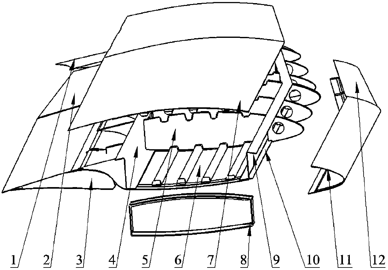
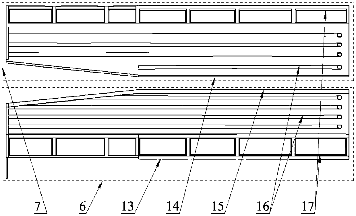
[0025] see Figure 1-Figure 3 , a fixed-wing UAV outer wing structure, including a wing box, the rear end of the wing box is connected to the flap 3, the aileron 2, and the winglet 1 in turn from the inside to the outside, and the front end of the wing box is connected from the inside to the outside. The front edge inner section 11 and the front edge outer section 12 in the shape of a forward bulge are arranged in turn from the inner side to the outer side. It is characterized in that the wing box has an upper wall plate 7, a lower wall plate 6 and a The front beam 9 at the front end of the wall plate 6 is connected to the rear beam 4 at the rear end of the upper wall plate 7 and the lower wall plate 6, and is supported on several ribs 5 extending longitudinally between the upper wall plate 7 and the lower wall plate 6 for connecting The joint 8 of the outer wing and the central wing; the opposite surfaces of the upper wall plate 7 and the lower wall plate 6 are provided with ...


PUM


Abstract

The invention discloses a fixed-wing unmanned aerial vehicle outer wing structure and a manufacturing method thereof. The fuel economy and the market competitiveness of a fixed-wing unmanned aerial vehicle are effectively improved. The outer wing structure comprises a wing box, the rear end of the wing box is connected with a wing flap, an aileron and a winglet, the front end of the wing box is provided with a forward uplifted front edge inner section and a front edge outer section, the wing box is provided with an upper wall plate, a lower wall plate, a front beam, a rear beam, a wing rib anda joint, the joint is used for connecting an outer wing with a central wing, horizontally extending foam stringers are arranged on opposite surfaces of the upper wall plate and the lower wall plate,grooves matched with the foam stringers are formed in the upper end and the lower end of a middle wing rib, the front beam and the rear beam are in 'Z' shapes, lower plates of the front beam and the rear beam oppositely extend and are fixed onto the lower wall plate, upper plates of the front beam and the rear beam reversely extend and are fixed onto the upper wall plate, web plates of the front beam and the rear beam are connected between the upper plate and the lower plate, and the wing rib comprises a front wing rib, the middle wing rib and a rear wing rib.

Description

technical field [0001] The invention relates to the technical field of unmanned aerial vehicles, in particular to an outer wing structure of a fixed-wing unmanned aerial vehicle and a manufacturing method thereof. Background technique [0002] In recent years, the development of intelligent machinery technology is in the ascendant, and drones, as aerial intelligent robots, have begun to be popularized in the civilian field. The vigorous development of the UAV market has accelerated the pace of survival of the fittest in the field of UAVs, and put forward higher requirements for the overall performance of UAVs, especially the economy and safety of UAVs. Fixed-wing UAV has the characteristics of high energy utilization rate and strong carrying capacity, and has an absolute advantage in engineering applications requiring long endurance, long range and heavy load. [0003] The wing is one of the most important components of a fixed-wing UAV. It is the main component that genera...

Claims


Application Information

Patent Timeline
Patent Type & Authority Applications(China)
IPC IPC(8): B64C3/18B64C3/26B64C3/20B64C3/28B64C9/00
CPCB64C3/187B64C3/20B64C3/26B64C3/28B64C9/00B64C2009/005Y02T50/40
Inventor 刘丹古江波陈键屈昌羽韩长京朱益佼胡瀚杰曾宪君张近黄圣璎董波舒娅
Owner CHONGQING GENERAL AVIATION IND GRP CO LTD
Learn More