
Intelligent parking system and control method thereof

A technology of intelligent parking and control method, which is applied in the field of intelligent parking system and its control, and can solve problems such as vehicle collision, friction, increased difficulty of other cars parking, collision, etc.

Active Publication Date: 2018-02-02
HEFEI SOFTEC AUTO ELECTRONICS
View PDF6 Cites 16 Cited by
  • Summary
  • Abstract
  • Description
  • Claims
  • Application Information

AI Technical Summary

Problems solved by technology

[0002] In recent years, with the process of automobile industrialization, the number of domestic automobiles has continued to rise. For the only parking spaces currently available, vehicles often deviate from parking due to human factors such as poor driving skills and bad parking habits. parking spaces or occupy multiple parking spaces, etc., which will often increase the difficulty of parking for other cars, resulting in accidents such as collisions and frictions between vehicles
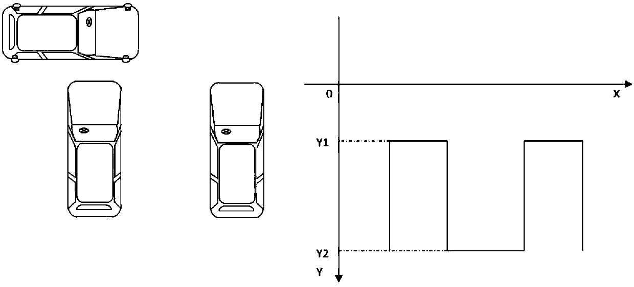
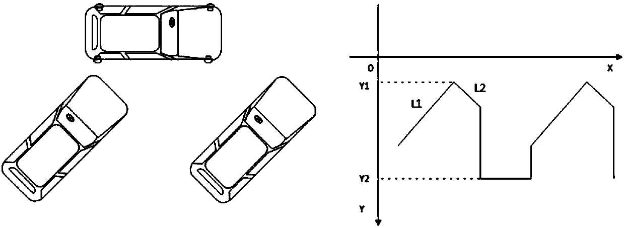
In response to the above situation, various intelligent parking assistance systems have emerged. The traditional parking space recognition is to judge the jump of the edge distance of the parking space through the radar probe installed on the side of the vehicle. When the vehicle passes the parking space, the radar probe works, and the system will follow The edge of the target parking space and its length and depth are identified by the distance jump, so as to plan the path model and assist the owner to park automatically, such as figure 1 shown; but at present, some parking spaces are arranged obliquely according to the environment and architectural planning, so the path model planned when using the traditional radar probe acquisition and processing is as follows figure 2 As shown, at this time, if the car is parked automatically according to the planned path, a collision will inevitably occur

Method used


Image

  • Intelligent parking system and control method thereof
  • Intelligent parking system and control method thereof
  • Intelligent parking system and control method thereof

Examples


Embodiment Construction

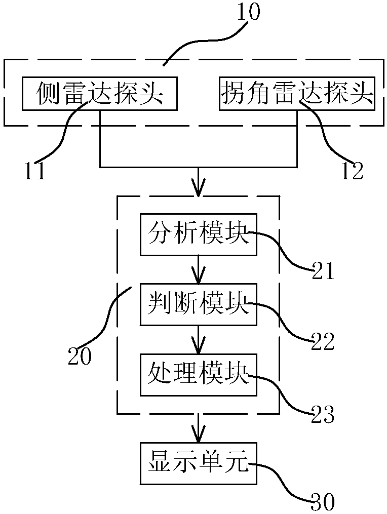
[0014] combined with Figure 3-5 The present invention is further described:

[0015] An intelligent parking system, including an information collection unit 10 and a control unit 20, the information collection unit 10 includes four side radar probes 11 arranged at the front and rear positions on both sides of the vehicle body and four corner radar probes 12 at the corners of the vehicle body , the side radar probe 11 and the corner radar probe 12 collect the current parking environment information and transmit it to the control unit 20, and the control unit 20 fuses the information collected by the adjacent side radar probe 11 and the corner radar probe 12 to calculate the body side of the parked vehicle to fit the edge of the parking space and plan the automatic parking path. The side radar probe 11 is combined with the corner radar probe 12 to collect the current parking environment information, and the corner radar probe 12 is arranged obliquely relative to the vehicle bo...


PUM


Abstract

The invention discloses an intelligent parking system and a control method thereof. The intelligent parking system comprises an information acquisition unit and a control unit. The information acquisition unit comprises four side radar probes positioned at the front positions and the back positions of the two side edges of a car body and four corner radar probes arranged at the corners of the carbody. The side radar probes and the corner radar probes collect current parking environment information to be transmitted to the control unit, and the control unit combines the information collected by the adjacent side radar probes and the corner radar probes to calculate boundary lines of car body side edges of parked cars, so that edges of parking spaces are fitted, and automatic parking pathsare planned. The corner radar probes are obliquely arranged relative to the car body, the boundary lines of the car body side edges of the parked cars in the inclined parking spaces can be detected through waving angles of the corner radar probes, algorithm fusion is conducted on the information collected by the adjacent side radar probes and the corner radar probes through the control unit, and the boundary lines of the car body side edges of the parked cars are calculated, so that contours of the parking spaces are stimulated, and the parking paths are planned.

Description

technical field [0001] The invention belongs to the technical field of automotive electronics, in particular to an intelligent parking system and a control method thereof. Background technique [0002] In recent years, with the process of automobile industrialization, the number of domestic automobiles has continued to rise. For the only parking spaces currently available, vehicles often deviate from parking due to human factors such as poor driving skills and bad parking habits. This will often increase the difficulty of parking for other cars, resulting in accidents such as collisions and frictions. In response to the above situation, various intelligent parking assistance systems have emerged. The traditional parking space recognition is to judge the jump of the edge distance of the parking space through the radar probe installed on the side of the vehicle. When the vehicle passes the parking space, the radar probe works, and the system will follow The edge of the target...

Claims


Application Information

Patent Timeline
Patent Type & Authority Applications(China)
IPC IPC(8): B60W30/06B62D15/02
CPCB60W30/06B62D15/0285
Inventor 许永华潘洋肖之炎梅炜炜
Owner HEFEI SOFTEC AUTO ELECTRONICS
Learn More