Buoyant Flying Body

An aircraft and floating technology, applied in the field of floating aircraft, can solve the problems of low mobility, inability to change the direction of movement flexibly, battery exhaustion, etc., and achieve the effect of high mobility

Inactive Publication Date: 2018-01-26
中村浩平
View PDF2 Cites 2 Cited by
  • Summary
  • Abstract
  • Description
  • Claims
  • Application Information

AI Technical Summary

Problems solved by technology

[0005] However, since the hot air balloon in the above-mentioned conventional aircraft does not have a power source for horizontal movement, the direction of movement is greatly affected by the wind, which is difficult to control and is not suitable for the transportation of goods and people.
In addition, since the airship is a horizontally long ellipsoid, the airship is vulnerable to wind resistance, and there is a problem that it cannot move flexibly and change directions.
[0006] In addition, there are also reports that conventional unmanned aircraft, including the unmanned aerial vehicle described in Patent Document 1, are exhausted due to battery exhaustion (the current average flight time is only about 20 minutes), or failure of the drive source, Or failures such as propeller damage, fall at a rate of about 1 in 20 times, the risk of accidents accompanying the fall, and the risk of aircraft damage are high.
In addition, although the movement in the vertical direction and the horizontal direction is performed by a common propeller, there is also a problem that the ability to move in the horizontal direction is low because the propeller is directed only up and down.
In addition, the propeller of the unmanned aircraft needs to be larger than the aircraft body, and there are problems such as noise and high risk of contact with people.

Method used


Image

  • Buoyant Flying Body
  • Buoyant Flying Body
  • Buoyant Flying Body

Examples


Embodiment Construction

[0032] Hereinafter, one embodiment of the floating aircraft according to the present invention will be described with reference to the drawings.

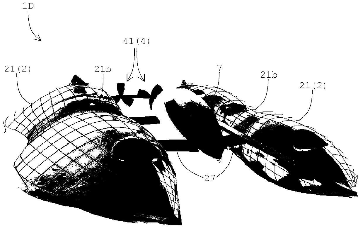
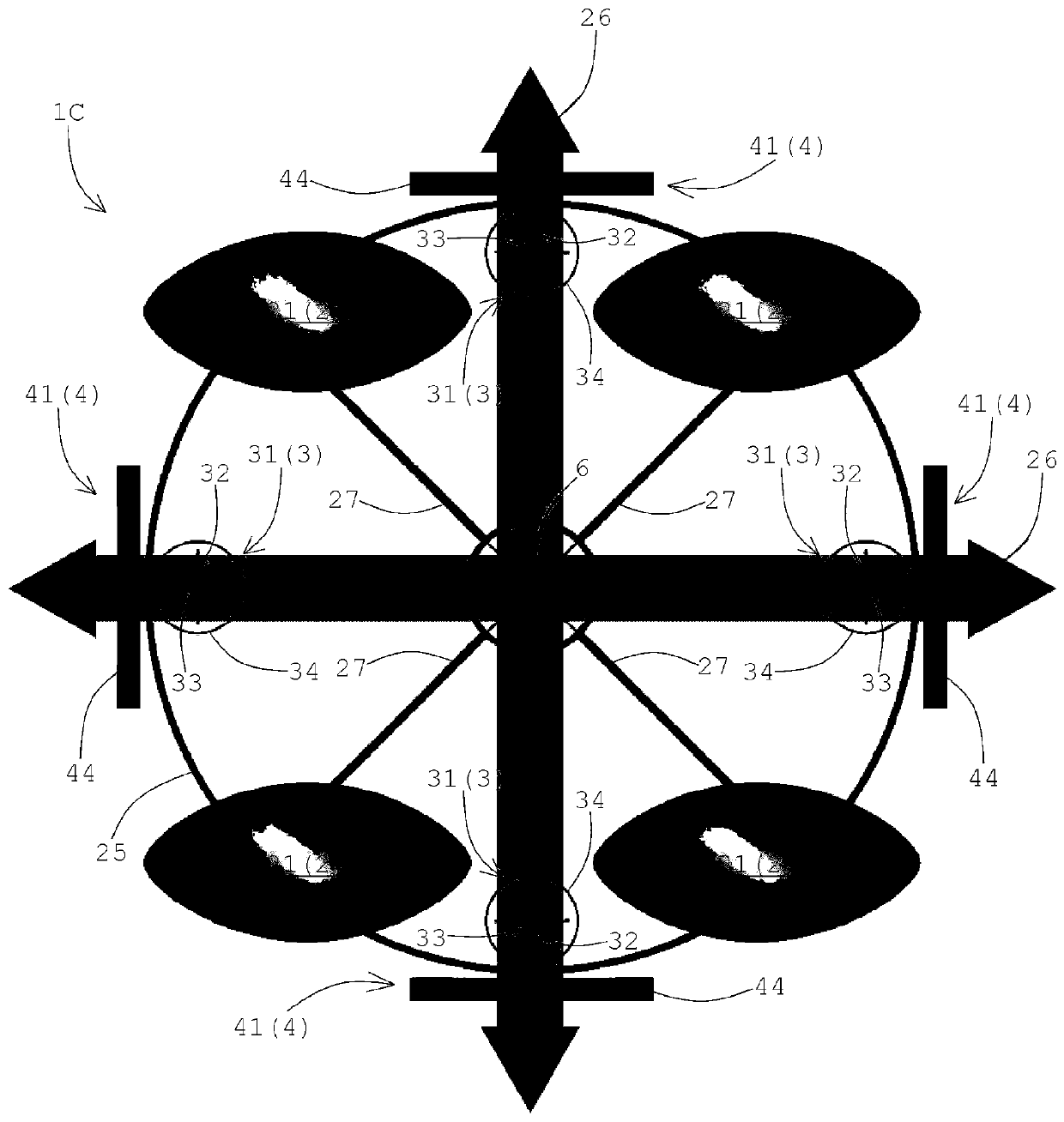
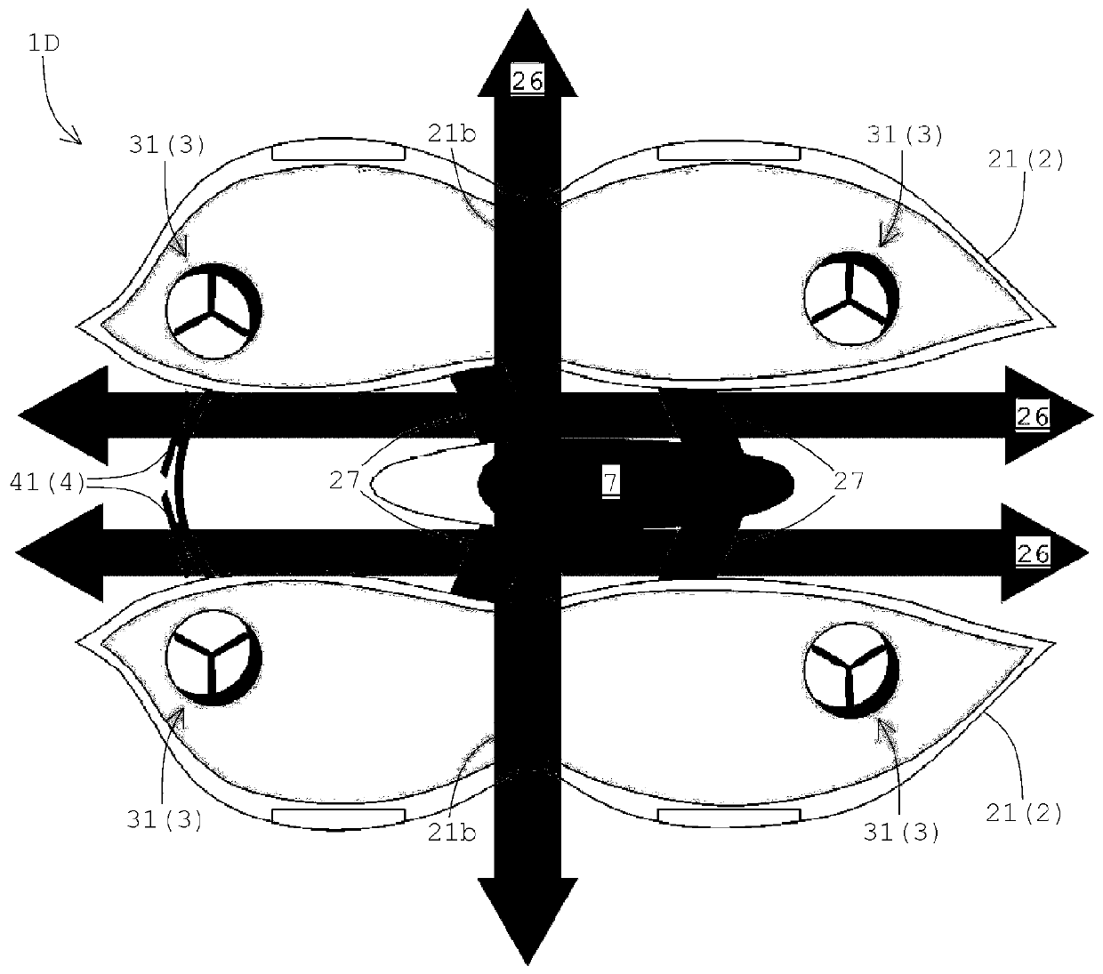
[0033] Such as figure 1 As shown, the floating aircraft 1A of the first embodiment has a floating body 2 in which a gas having a specific gravity smaller than air is sealed inside, a vertical propulsion propeller group 3 for imparting a vertical propulsion force to the floating body 2, and a pair of The above-mentioned floating body 2 provides a propulsion force in the horizontal direction, and the horizontal propulsion propeller group 4, and the temperature adjustment mechanism 5 that regulates the temperature of the gas in the above-mentioned floating body 2. Each configuration will be described below.

[0034] The floating body 2 seals a gas with a specific gravity smaller than air inside, thereby obtaining buoyancy with the help of the specific gravity difference between the surrounding air and the gas, and is easy to float in ...


PUM


Abstract

To provide a buoyant flying body such that the risk of crashing can be reduced in order to ensure a high level of safety, and motion control can be facilitated by reducing the influence of wind in order to exert a high level of mobility. A buoyant flying body having a buoyant main body in which a gas having a smaller specific gravity than air is sealed, vertical propulsion propellers for providingvertical propulsion to the buoyant main body, and horizontal propulsion propellers for providing horizontal propulsion to the buoyant main body, wherein the buoyant main body forms horizontal wind passages at least in two direction, and outer peripheral edges thereof respectively form an acute angle in a side view.

Description

technical field [0001] The present invention relates to a floating aircraft for transporting goods and people, aerial photography, and the like. Background technique [0002] Conventionally, hot-air balloons, airships, and the like are known as floating-type aircraft. These flying machines float and fly by utilizing the difference in specific gravity between the gas filled in the balloon and the outside air to obtain buoyancy. [0003] In addition, in recent years, research and development on an unmanned aerial vehicle called a so-called drone (drone) for the purpose of cargo delivery and aerial photography has been advanced. For example, in Japanese Unexamined Patent Application Publication No. 2014-227016, an invention is proposed regarding a remote-controlled unmanned aerial vehicle equipped with a propeller that generates lift by rotation, and a drive source that rotates the propeller. , and a control mechanism for controlling the driving source (Patent Document 1). ...

Claims


Application Information

Patent Timeline
Patent Type & Authority Applications(China)
IPC IPC(8): B64B1/30B64C25/06B64C27/08B64C39/02
CPCB64C25/06B64C27/08B64B1/30B64C39/024B64B1/58B64U10/30B64U30/20B64U2101/30B64U10/13B64C39/02
Inventor 中村浩平
Owner 中村浩平
Why Eureka
Try Eureka