Method and device for data transmission
A transmission method and transmission equipment technology, applied in the field of data transmission, can solve problems such as overtime retransmission of data packets, technical problems that cannot solve real-time transmission, network congestion, etc.
- Summary
- Abstract
- Description
- Claims
- Application Information
AI Technical Summary
Problems solved by technology
Method used
Image


Examples
Embodiment 1
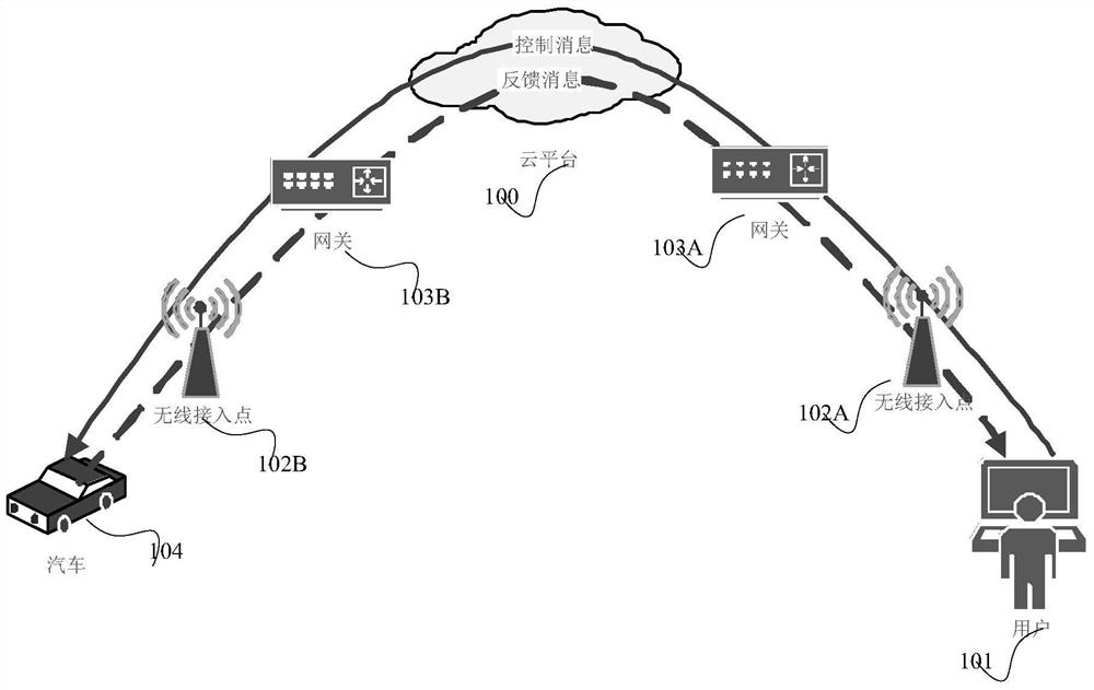
[0045] figure 2 An application scenario of the embodiment of the present invention is given. In this scenario, the user 101 accesses the IoT cloud platform 100 through the wireless access point 102A, and sends the user 101 control message to the car 104 . After successfully receiving the order, the car 104 feeds back the successful reception information to the user 101, and automatically goes to the designated place. User control messages in the physical network are extremely sparse, that is, only a few data packets need to be transmitted for a long period of time. Because of the sparseness, these messages cannot trigger the fast retransmission mechanism of TCP. Once lost, they can only rely on the TCP timeout retransmission mechanism to complete the transmission. And because the wireless channel environment is relatively bad, the control message using the TCP protocol may need multiple timeouts to be successfully sent, which greatly increases the transmission time delay of...
Embodiment 2
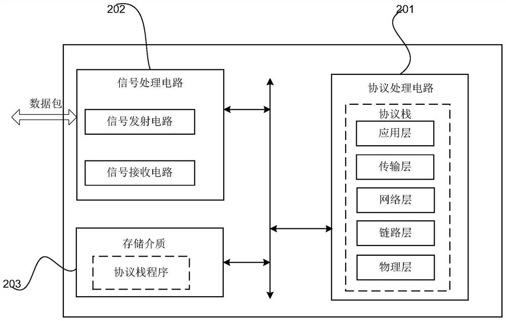
[0049]In combination with the application scenario of Embodiment 1, Embodiment 2 of the present invention provides various network element architectures in reality. The implementation of the embodiment of the present invention needs to change the protocol stack in the existing network element. A network element may be any device supporting the TCP protocol, such as a general computer (including a processor and a memory), a terminal device, and a server. The schematic diagram of a network element architecture is as follows: image 3 As shown, it includes a protocol processing circuit 201 , a signal processing circuit 202 and a storage medium 203 . The protocol processing circuit 201 is used to process digital information, the signal processing circuit 202 is used to process the receiving and sending of physical signals, and the storage medium 203 is used to store data and programs required in the process of information interaction. Programs can be understood as: instructions,...
Embodiment 3
[0056] Combining the application scenario of Embodiment 1 and the hardware architecture of Embodiment 2, Figure 4 It is a schematic diagram of the architecture principle of a data transmission method provided in Embodiment 3 of the present invention, as shown in Figure 4 as shown,
[0057] When data needs to be transmitted, the application directly specifies the service type to be transmitted by the sender, or the sender obtains the service type of the data to be transmitted according to the characteristic variable of the data flow. Alternatively, the sending end may acquire a preset service type.
[0058] The sending end obtains the corresponding delay requirement according to the service type, and sets the total transmission time of the redundant data packets of each data packet as a period of time related to the delay requirement.
[0059] The sending end calculates the number of redundant data packets for each data packet according to the acquired network state variabl...
PUM
 Abstract
Description
Claims
Application Information
 - Generate Ideas
- Intellectual Property
- Life Sciences
- Materials
- Tech Scout
- Unparalleled Data Quality
- Higher Quality Content
- 60% Fewer Hallucinations
Browse by: Latest US Patents, China's latest patents, Technical Efficacy Thesaurus, Application Domain, Technology Topic, Popular Technical Reports.
© 2025 PatSnap. All rights reserved.Legal|Privacy policy|Modern Slavery Act Transparency Statement|Sitemap|About US| Contact US: help@patsnap.com