
Auxiliary positioning device of laser coding machine

A technology of laser coding machine and auxiliary positioning, applied in the field of laser coding machine, can solve the problems of poor coding effect, unclear pattern or text, etc.

Inactive Publication Date: 2018-01-26
XINCHANG COUNTY CHENGTAN TOWN BONA MACHINERY PLANT
View PDF0 Cites 1 Cited by
  • Summary
  • Abstract
  • Description
  • Claims
  • Application Information

AI Technical Summary

Problems solved by technology

[0002] The laser coding machine gathers the laser on the surface of the object to be marked with extremely high energy density, vaporizes the material on the surface through burning and etching, and precisely burns out the pattern by controlling the effective displacement of the laser beam Or text, but if the positioning is not accurate, the coding effect will be poor, and even the engraved pattern or text is not clear, and there are certain deficiencies

Method used


Image

  • Auxiliary positioning device of laser coding machine

Examples


Embodiment

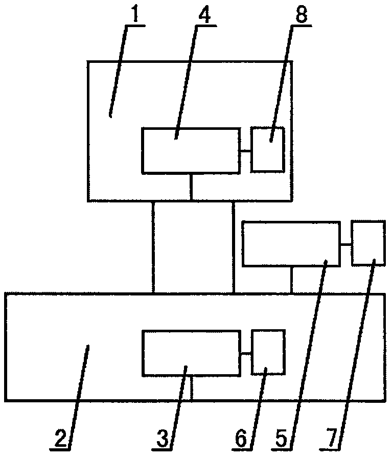
[0012] Embodiment: as shown in the accompanying drawing. An auxiliary positioning device for a laser coding machine, comprising a body (1), on which a conveying module (2), a fixing module (3), a camera module (4), and a management module (5) are arranged. , the conveying module (2) is set on the automatic production line to convey the object to the scanning area of ​​the camera of the laser coding machine, the fixed module (3) fixes it in a certain position, the camera module (4) is used to scan the image of the object, and finally scans The received image information is sent to the management module (5) for processing.

[0013] An auxiliary positioning device for a laser coding machine, in which a positioning adjustment device (6) is arranged on a fixed module (3) for adjusting the placement position of objects.

[0014] An auxiliary positioning device for a laser coding machine, which is provided with a prompt module (7), which sends a prompt message when the movement of t...


PUM


Abstract

The invention discloses an auxiliary positioning device of a laser coding machine. The auxiliary positioning device comprises a machine body (1), and the machine body (1) is provided with a conveyingmodule (2), a fixing module (3), a camera module (4) and a management module (5). When the auxiliary positioning device is in operation, the conveying module (2) is arranged on an automatic productionline and conveys a product to a camera scanning area of the laser coding machine, the product is fixed to one position through the fixing module (3), the camera module (4) is used for scanning the image of the product, image information obtained finally through scanning is sent to the management module (5) to be processed, and a positioning adjusting device (6) is arranged on the fixing module (3) to be used for adjusting the placing position of the product. Stable positioning of the product can be achieved, the definition of patterns or words coded by the laser coding machine can be more effectively ensured, and the coding effect is improved.

Description

technical field [0001] The invention relates to a laser coding machine. Background technique [0002] The laser coding machine gathers the laser on the surface of the object to be marked with extremely high energy density, vaporizes the material on the surface through burning and etching, and precisely burns out the pattern by controlling the effective displacement of the laser beam Or text, but if the positioning is not accurate, the coding effect will be poor, and even the engraved pattern or text is not clear, which has certain shortcomings. Contents of the invention [0003] The purpose of the present invention is to provide an effective auxiliary positioning device for a laser marking machine. [0004] The present invention is achieved like this. An auxiliary positioning device for a laser coding machine, which includes a body on which a conveying module, a fixing module, a camera module, and a management module are arranged. During operation, the conveying module i...

Claims


Application Information

Patent Timeline
IPC IPC(8): B41J2/435B41J29/393
Inventor 蔡文武
Owner XINCHANG COUNTY CHENGTAN TOWN BONA MACHINERY PLANT
Learn More