
Fast-switchable mechanical arm structure

A technology of fast switching and manipulators, applied in the direction of manipulators, chucks, manufacturing tools, etc., can solve the problems of cumbersome replacement of manipulators, achieve the effect of increasing the range of suction, ensuring repeatability, and reducing weight

Pending Publication Date: 2018-01-26
SOHBI CRAFT CHANGSHU
View PDF9 Cites 6 Cited by
  • Summary
  • Abstract
  • Description
  • Claims
  • Application Information

AI Technical Summary

Problems solved by technology

However, the process of replacing the manipulator is still very cumbersome

Method used


Image

  • Fast-switchable mechanical arm structure
  • Fast-switchable mechanical arm structure
  • Fast-switchable mechanical arm structure

Examples


Embodiment Construction

[0024] The implementation of the present invention will be illustrated by specific specific examples below, and those skilled in the art can easily understand other advantages and effects of the present invention from the contents disclosed in this specification.

[0025] see Figure 1 to Figure 6 . It should be noted that the structures, proportions, sizes, etc. shown in the drawings attached to this specification are only used to match the content disclosed in the specification, for those who are familiar with this technology to understand and read, and are not used to limit the implementation of the present invention. Limiting conditions, so there is no technical substantive meaning, any modification of structure, change of proportional relationship or adjustment of size, without affecting the effect and purpose of the present invention, should still fall within the scope of the present invention. The disclosed technical content must be within the scope covered. At the sa...


PUM


Abstract

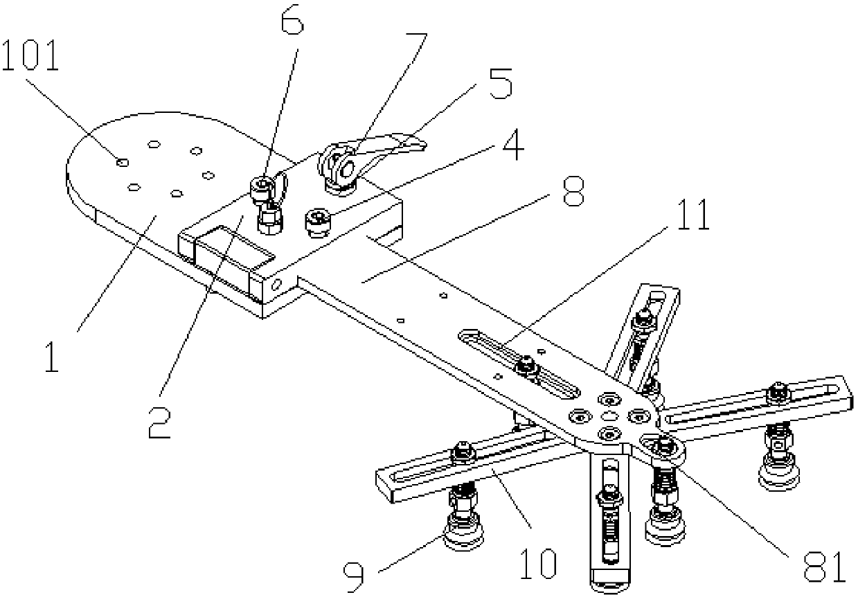
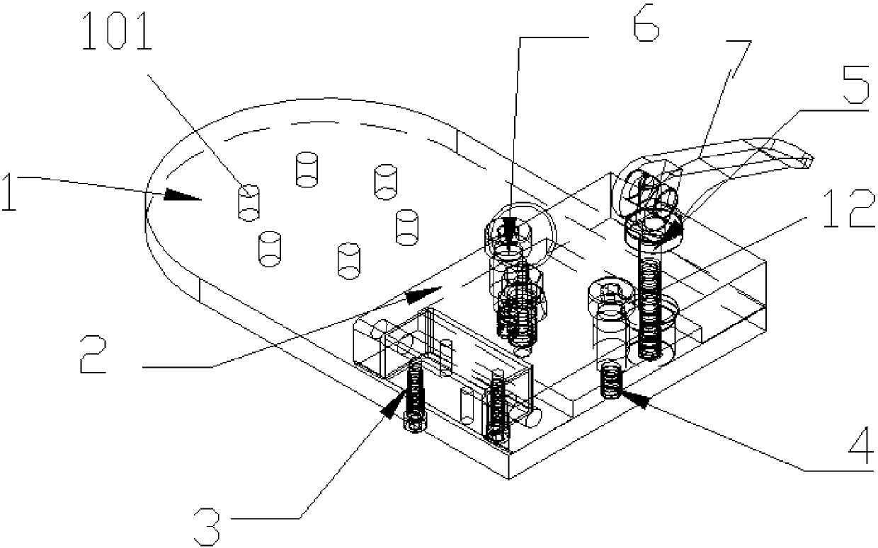
The invention provides a fast-switchable mechanical arm structure. The fast-switchable mechanical arm structure comprises a base, a clamping device, an arm body and a hinge block. The clamping devicecomprises a locking block, a cam handle, a positioning screw and an indexing pin. The positioning screw penetrates the locking block and is connected with the base. The hinge block is fixed to the base. The locking block is hinged to the hinge block. A groove for containing the head end of the arm body is formed in the locking block. The head end of the arm body is placed in the groove, and a grabbing mechanism is arranged at the other end of the arm body. The cam handle penetrates the locking block and is connected with the base. By the adoption of the fast-switchable mechanical arm structure, the number of applicable products is large, the switching time is short, and the weight of a mechanical arm is reduced due to a hollow structure.

Description

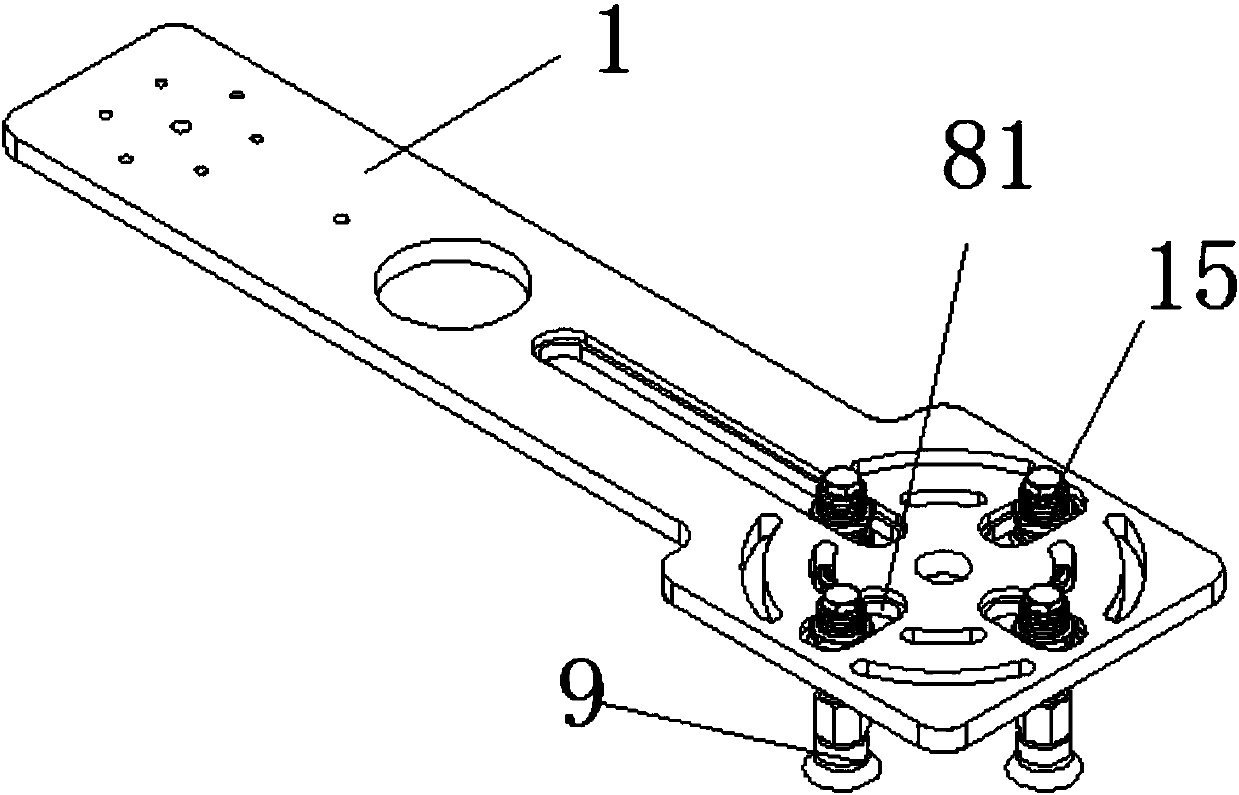
technical field [0001] The invention relates to a fast-switchable manipulator structure. Background technique [0002] When the robot grabs the product, it needs to install a manipulator on the jig installation place of the robot, and complete the material picking action through the suction cup, electromagnet or fixture on the manipulator. The manipulator in the prior art is usually fixed to the robot by means of screws, or fixed in the elongated groove of the manipulator by an end suction cup or an electromagnet. Such as figure 1 As shown, it is a common structure of existing manipulators. The arm body is provided with several circular clamping grooves. Studs and nuts are arranged in the circular clamping grooves. The lower end of the studs is provided with a suction cup. The replacement of the arm body is to disassemble and assemble the manipulator by screwing, and the switching time is long. In addition, the fixing part of the suction cup in the prior art is limited by...

Claims


Application Information

Patent Timeline
Patent Type & Authority Applications(China)
IPC IPC(8): B25J15/00B25J15/06
Inventor 曹迎军张宁森本元气顾宇钧杨志军李阳
Owner SOHBI CRAFT CHANGSHU
Learn More