Welding manipulator

A technology for welding manipulators and racks, which is applied in the direction of manipulators, program-controlled manipulators, welding equipment, etc., which can solve the problems of inability to achieve high precision, high speed, high stability, and small welding space, so as to provide welding quality and improve work efficiency , the effect of improving the utilization rate

Pending Publication Date: 2018-01-26
浙江斯柯特科技有限公司
View PDF0 Cites 0 Cited by
  • Summary
  • Abstract
  • Description
  • Claims
  • Application Information

AI Technical Summary

Problems solved by technology

There is a fixed welding torch at the end of the welding manipulator, which can realize the function of automatic welding. The welding space in the existing welding manipulator is small, and it cannot meet the welding requirements of high precision, high speed and high stability.

Method used


Image

  • Welding manipulator
  • Welding manipulator

Examples


Embodiment Construction

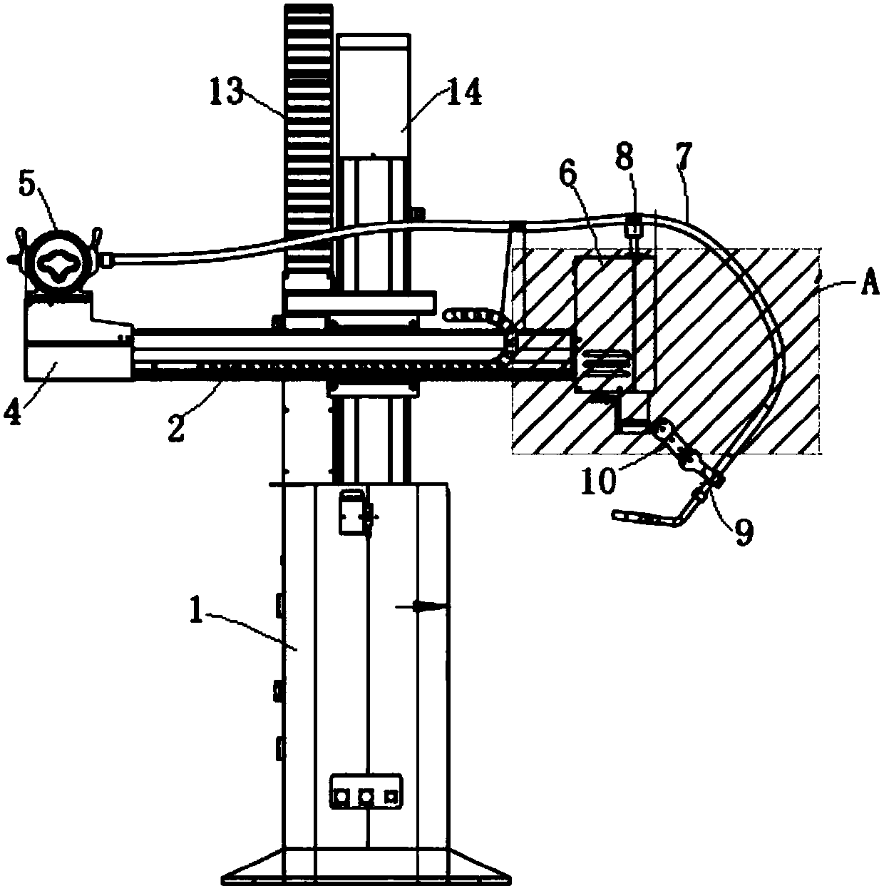
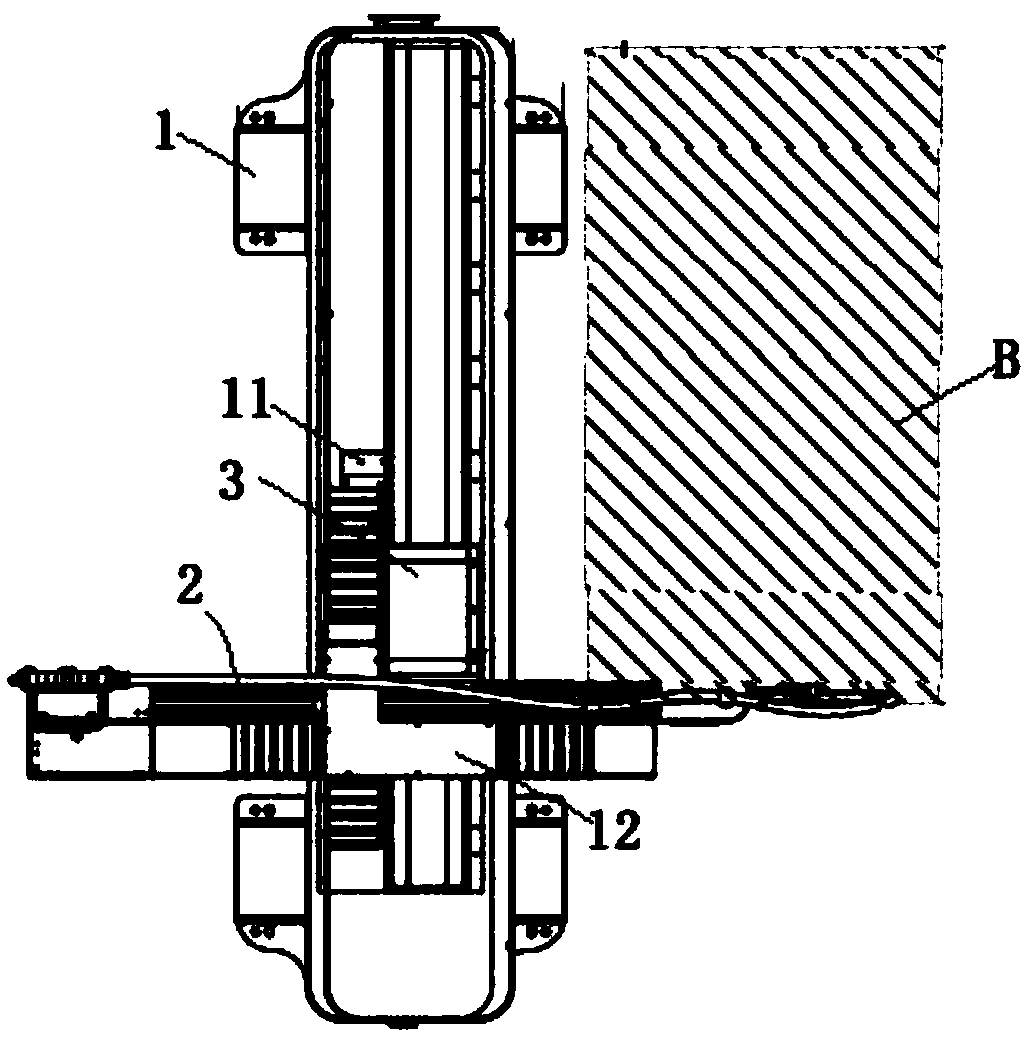
[0022] Such as figure 1 , figure 2 As shown, a welding manipulator includes a frame 1 on which an X-axis linear module, a Y-axis linear module and a Z-axis linear module are arranged. The X-axis linear module includes a The X-axis guide rail 2, the X-axis guide rail 2 connects the transmission part 3 and the driving part, the end of the X-axis guide rail 2 is provided with a sliding block 4, the welding machine 5 is fixed on the sliding block 4, and the other side of the X-axis guide rail 2 is provided with Fixing block 6, welding hose 7 is connected to welding machine 5, welding head is placed at the end of welding hose 7, the middle part of welding hose 7 is connected with the top of fixing block 6 through upper fixing foot 8, welding hose 7 is close to the end The position of the head is provided with a first living hinge 9, the bottom of the fixed block 6 is provided with a second living hinge 10, and the first living hinge 9 is movably connected with the second living h...


PUM


Abstract

The invention relates to a welding manipulator. The welding manipulator comprises a rack. An X-axis linear module, a Y-axis linear module and a Z-axis linear module are arranged on the rack. The X-axis linear module comprises an X-axis guide rail arranged on the rack. The X-axis guide rail is connected with a transmission component and a driving component. The end of the X-axis guide rail is provided with a sliding block. A welding machine is fixed to the sliding block. The other side of the X-axis guide rail is provided with a fixed block. A welding hose is connected to the welding machine. The end head of the welding hose is provided with a welding head. The middle portion of the welding hose is connected with the top of the fixed block through an upper fixing foot. The position, close to the end head, of the welding hose is provided with a first movable hinge piece. The bottom of the fixed block is provided with a second movable hinge piece. The first movable hinge piece and the second movable hinge piece are connected movably. The mass-produced linear modules developed independently are adopted for the X-axis, the Y-axis and the Z-axis. Through secondary structure combination design, the strength of equipment is improved, high-speed operation is smoother and steadier.

Description

technical field [0001] The invention relates to mechanical equipment, in particular to a welding manipulator. Background technique [0002] The welding manipulator is a kind of automation equipment, in which the arm is the basic part of the robot manipulator, which can perform rotating and reciprocating movements. There is a fixed welding gun at the end of the welding manipulator, which can realize the function of automatic welding. The welding space in the existing welding manipulator is small, and it cannot meet the welding requirements of high precision, high speed and high stability. Contents of the invention [0003] The object of the present invention is to provide a welding manipulator in order to solve the defects in the prior art. [0004] In order to achieve the above object, the technical scheme adopted in the present invention is: [0005] A welding manipulator comprising a frame on which an X-axis linear module, a Y-axis linear module, and a Z-axis linear mo...

Claims


Application Information

Patent Timeline
IPC IPC(8): B23K37/02B25J5/02B25J11/00B25J15/00B25J9/00
Inventor 朱捷安
Owner 浙江斯柯特科技有限公司
Why Eureka
Try Eureka