Transparent soil model test device for simulating tunnel excavation deformation and test method

A model test device and tunnel excavation technology, which is applied in the direction of measuring devices, instruments, scientific instruments, etc., can solve the problem that the deformation characteristics of the model cannot be directly observed, and achieve the effects of small size, reasonable system setting, and convenient test operation

Active Publication Date: 2018-01-23
CHONGQING UNIV
View PDF8 Cites 9 Cited by
  • Summary
  • Abstract
  • Description
  • Claims
  • Application Information

AI Technical Summary

Benefits of technology

This technology solves problems with existing methods for testing tunnels but it cannot measure any changes caused by surrounding factors like water or air pressure on their surface due to limitations such as large geometry and lack of realistically representative environmental variables. It allows researchers to see how these forces affects the movement of sediment near underground structures while they are being built up through simulations rather than relying solely on physical measurements alone.

Problems solved by technology

The patent text discusses the challenges faced in tunnel engineering, specifically the deformation and destruction of tunnels during construction. The current mathematical mechanics methods can only provide solutions for simple tunnel projects, and even then, these solutions need to be verified with on-site measurements and model tests. Model tests are beneficial as they provide a realistic representation of the stress and displacement fields in actual working conditions. However, traditional model tests can only observe the macroscopic deformation and boundary areas, not the internal deformation. The use of transparent soil technology allows for the visual study of three-dimensional deformation and strength of the model, providing valuable insights into the deformation and failure mechanisms of surrounding rock caused by tunnel excavation. The synthetic transparent soil material used in these tests has properties similar to real soil and good transparency. The use of PIV technology accurately measures the displacement field of the soil. Overall, the patent text aims to address the technical problems related to understanding and optimizing tunnel design and construction schemes through tunnel model tests using transparent soil materials.

Method used


Image

  • Transparent soil model test device for simulating tunnel excavation deformation and test method
  • Transparent soil model test device for simulating tunnel excavation deformation and test method
  • Transparent soil model test device for simulating tunnel excavation deformation and test method

Examples


Embodiment 1

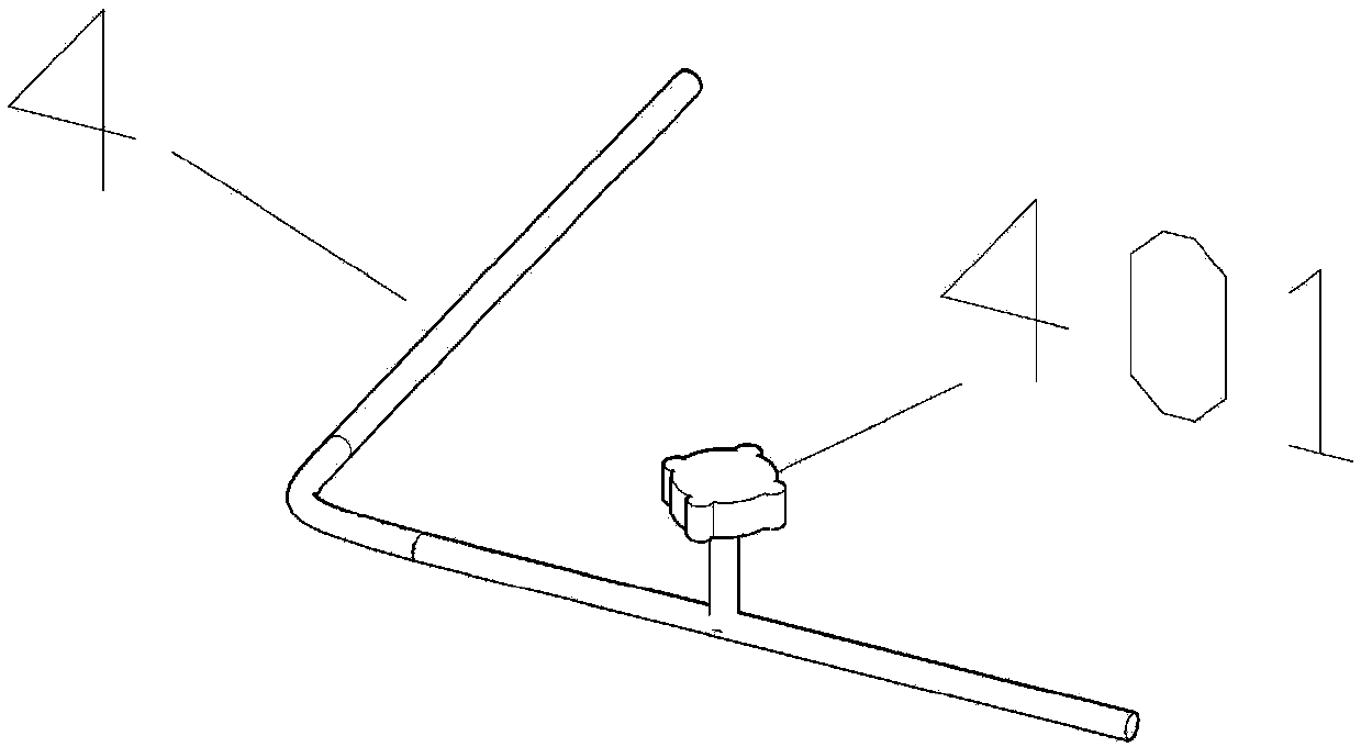
[0043] A transparent soil model test device for simulating tunnel excavation deformation, which is characterized in:

[0044] It mainly includes transparent model box 1, rubber thin-walled round pipe 3, drain pipe 4, industrial camera I5, industrial camera II50, laser transmitter I6, laser transmitter II60 and optical platform 7.

[0045] See figure 1 , The transparent model box 1 is made of plates, and the transparent model box is made of plexiglass. The upper end is open, and the four sides are defined as the front, rear, left, and right sides respectively [the definition It is for the convenience of description to express the positional relationship of the four faces]. The transparent model box 1 is made of organic glass. The left and right side panels and the bottom panel are glued together. The panels on both sides of the circular opening I101 and the circular opening II102 are bolted to the left and right panels and the bottom plate. The panels on both sides can be removed...

Embodiment 2

[0055] This embodiment discloses a test method based on the test device described in embodiment 1, which is characterized in that it includes the following steps:

[0056] 1) Make transparent model box 1, thin-walled rubber cylinder 3 and drain pipe 4 according to the designed size.

[0057] 2) Fill the thin-walled rubber cylinder 3 with water, and place it upside down so that the bottom surface of the opening 301 faces upward.

[0058] 3) Connect the thin-walled rubber cylinder 3 to the drain pipe 4, and do waterproof sealing treatment to the connection.

[0059] 4) Pass the thin-walled rubber cylinder 3 through the opening 101 of the transparent model box 1 and place it in the box body, and do a waterproof sealing treatment on the interface.

[0060] 5) Prepare transparent soil 2 in the transparent model box 1 to the design height. After preparation, let it stand for 24 hours. In the embodiment, the preparation method of the transparent soil 2 is: pour the prepared mixture of white ...


PUM

PropertyMeasurementUnit
Particle sizeaaaaaaaaaa

Abstract

The invention provides a transparent soil model test device for simulating tunnel excavation deformation and a test method. The device comprises a transparent model box which can be fixed on an optical platform, a thin-wall rubber cylinder and a drain pipe. The transparent model box adopts a box body formed by splicing plates. Circular openings are formed in the two side walls of the box body. Anopening is formed in the edge of the bottom surface on one side of the thin-wall rubber cylinder. The thin-wall rubber cylinder penetrates through the openings in the transparent model box. A valve isarranged on the drain pipe. The drain pipe is connected to the opening in the thin-wall rubber cylinder. Two industrial cameras and two laser emitters are arranged outside the transparent model box.The valve on the drain pipe is opened during testing, and water in the thin-wall rubber cylinder is drained into a flash with scales separately. Laser emitted by the two laser emitters forms two transparent soil speckle fields in transparent soil. The industrial cameras records changes of the transparent soil speckle fields.

Description


Claims


Application Information

Patent Timeline
Owner CHONGQING UNIV
Why Eureka
Try Eureka