Fabricated building

A prefabricated and architectural technology, applied in buildings, building components, building structures, etc., can solve the problems of unguaranteed construction quality, serious environmental pollution, and high construction costs, and achieve convenient and fast installation, uniform quality, and simplified construction procedures. Effect

Active Publication Date: 2018-01-23
柏秋
View PDF8 Cites 4 Cited by
  • Summary
  • Abstract
  • Description
  • Claims
  • Application Information

AI Technical Summary

Problems solved by technology

[0003] (1) The technical problems to be solved by the present invention are: the traditional method of pouring concrete on site has large transportation volume, high construction cost, no guarantee of construction quality, serious environmental pollution, high cost, and easily causes problems such as energy waste

Method used


Image

  • Fabricated building
  • Fabricated building
  • Fabricated building

Examples


Embodiment 1

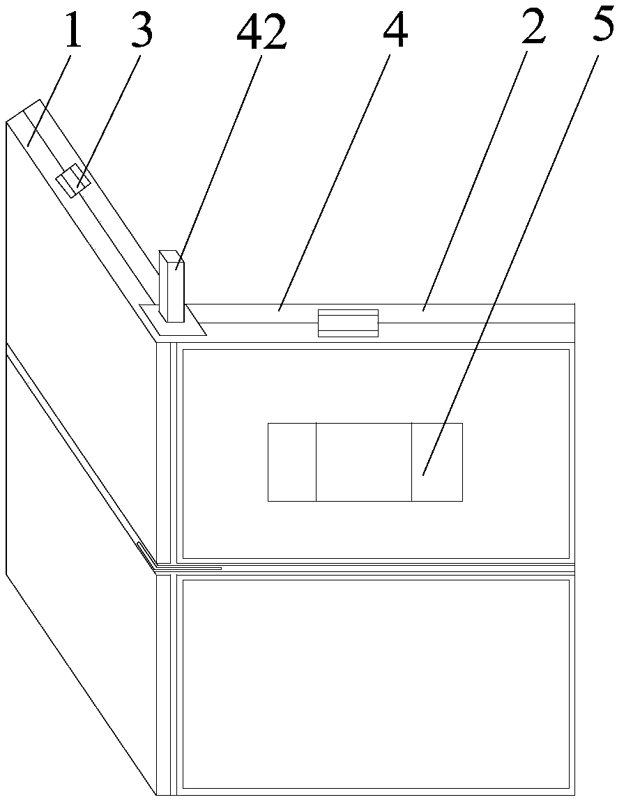
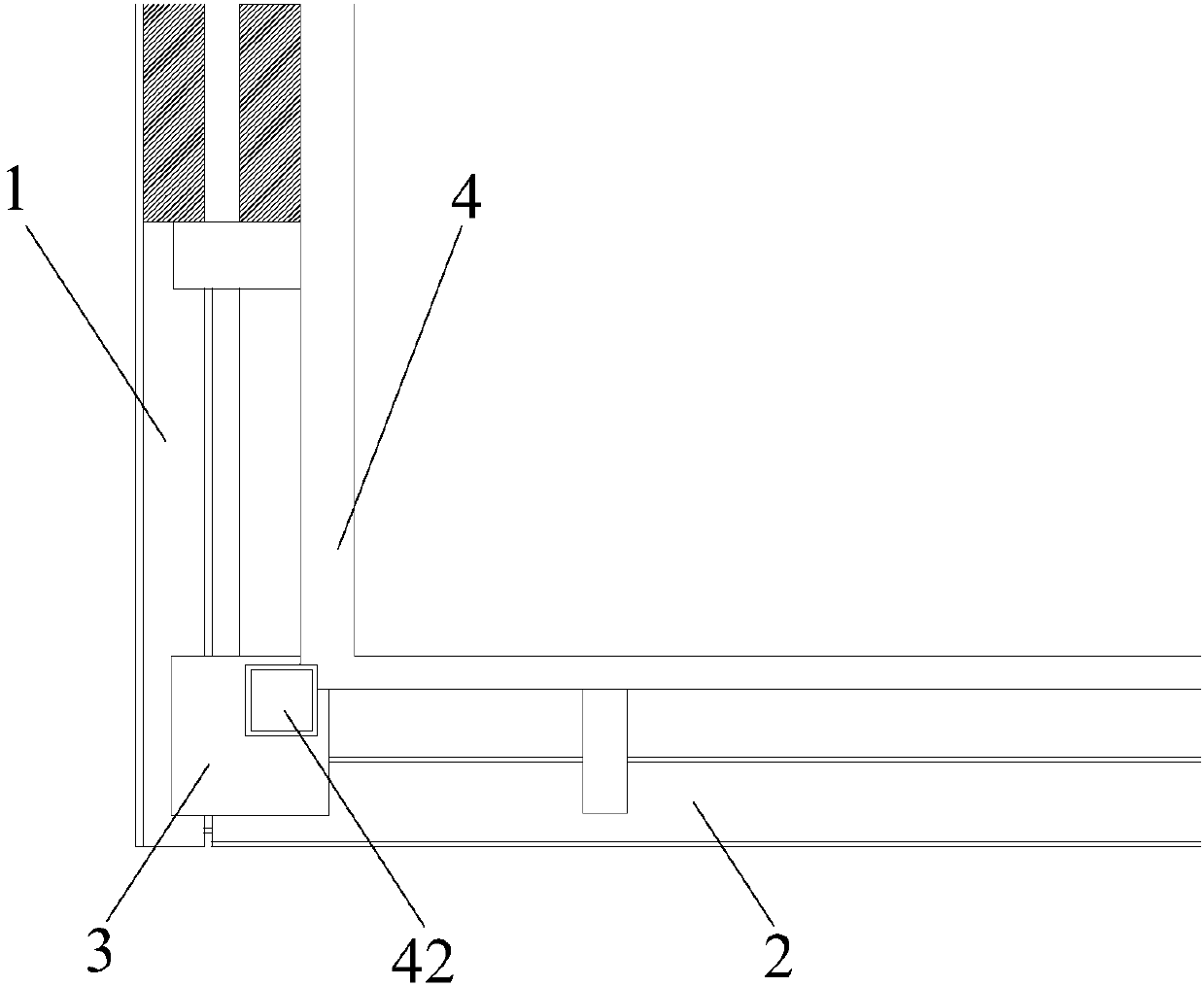
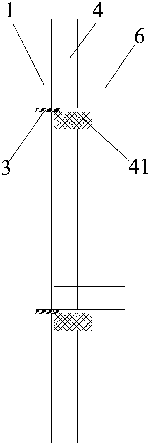
[0039] Such as Figure 6 As shown, the present invention provides a prefabricated building, comprising a steel structure frame 4 and prefabricated exterior wall panels, specifically as Figure 6 As shown, the steel structure frame 4 is a rectangular frame, and the exterior wall panels include four walls connected end to end in sequence, each side wall is provided with a first wall panel 1, and the four first wall panels The boards 1 are respectively connected to the outside of the steel structure frame 4 through connectors 3, and the bottom end of the channel steel frame on each of the first wall boards 1 is connected to the adjacent first wall board 1. The welding parts 19 on the top are welded; in this way, the first wall panel 1 is prefabricated in the factory, so that there is no need to pour concrete on site to manufacture the cavity, which can solve the problem of large transportation volume, high construction cost and high construction cost of the method of pouring conc...

Embodiment 2

[0047] This embodiment is substantially the same as the technical solution in Embodiment 1, the main difference is that the exterior wall panel in this embodiment includes both the first wall panel 1 and the second wall panel 2, and the exterior wall panel also includes the first wall panel Two wallboards 2, the second wallboard 2 includes a frame-shaped second channel steel frame 28 and a second wall, and the second channel steel frame 28 is sleeved on the outside of the second wall; The two walls include the third fiberglass mesh layer 22, the third steel wire mesh layer 22, the third cement foam layer 23, the second thermal insulation layer 24, the fourth cement foam layer 25, the fourth fiberglass mesh layer 22 connected from top to bottom. Steel mesh layer 26 and fourth fiberglass mesh layer 27 .

[0048] The steel structure frame 4 is a rectangular frame, and the exterior wall panel includes a first wall, a second wall, a third wall and a fourth wall connected end to end...


PUM


Abstract

The invention relates to the technical field of buildings, in particular to a fabricated building. The fabricated building comprises a steel structure frame and prefabricated external wall plates. Themultiple layers of external wall plates are arranged from top to bottom, and each layer of external wall plate is fixed to the outer side of the steel structure frame through a connection part. By fixing the prefabricated external wall plates to the steel structure frame to form the building, the problems that an in-situ concrete pouring method is large in transporting amount and high in construction cost, the construction quality cannot be ensured, environmental pollution is serious, the cost is high, energy waste is prone to being generated can be solved. The external wall plates are transported to a construction site after being prefabricated in a factory, and mounted by adopting hoisting in the construction site to assemble an overall building, thus achievement of housing industrialization is facilitated, and the defects of in-situ formwork building, reinforcement assembling and concrete pouring of a traditional construction method are overcome. Mounting of windows and doors and construction of heat preservation layers and decoration layers are not needed after the main structure of the building is completed, and thus the construction procedures are simplified.

Description

technical field [0001] The invention relates to the technical field of buildings, in particular to a prefabricated building. Background technique [0002] The current residential construction adopts the method of pouring concrete on site. The on-site construction of the main structure of the outer wall generally needs to go through the construction process of supporting formwork, laying steel bars, pouring concrete and then removing the formwork. A series of tedious work such as thermal insulation layer construction, exterior decoration layer construction and interior decoration construction. On-site construction may cause a lot of energy waste, such as the loss and waste of coal, water, steel, concrete and pasture, and also generate a lot of construction waste. Each project needs to use many transport vehicles to transport a large amount of construction raw materials from outside the city to After the construction is completed, a large amount of construction waste is trans...

Claims


Application Information

Patent Timeline
Patent Type & Authority Applications(China)
IPC IPC(8): E04B2/58E04C2/38E04C2/284E04B1/682
CPCY02A30/00Y02B30/90
Inventor 柏秋柏晓臣
Owner 柏秋
Why Eureka
Try Eureka