Heat dissipation type switch cabinet with sweeping function

A switchgear and heat-dissipating technology, applied in the field of heat-dissipating switchgear, can solve problems such as short circuit of switchgear and inability to clean in time, and achieve the effect of prolonging service life

Active Publication Date: 2018-01-19
南京永合电力科技有限公司
View PDF3 Cites 3 Cited by
  • Summary
  • Abstract
  • Description
  • Claims
  • Application Information

AI Technical Summary

Problems solved by technology

[0006] In order to overcome the disadvantages in the prior art that external air and dust enter the switch cabinet and cannot be cleaned in time, resulting in short circuit and other problems in the switch cabinet, the technical problem to be solved by the invention is to provide a switch cabinet working It can not only dissipate heat at any time, but also can clean the inside of the switch cabinet with a heat dissipation switch cabinet with cleaning function.

Method used


Image

  • Heat dissipation type switch cabinet with sweeping function
  • Heat dissipation type switch cabinet with sweeping function
  • Heat dissipation type switch cabinet with sweeping function

Examples


Embodiment 1

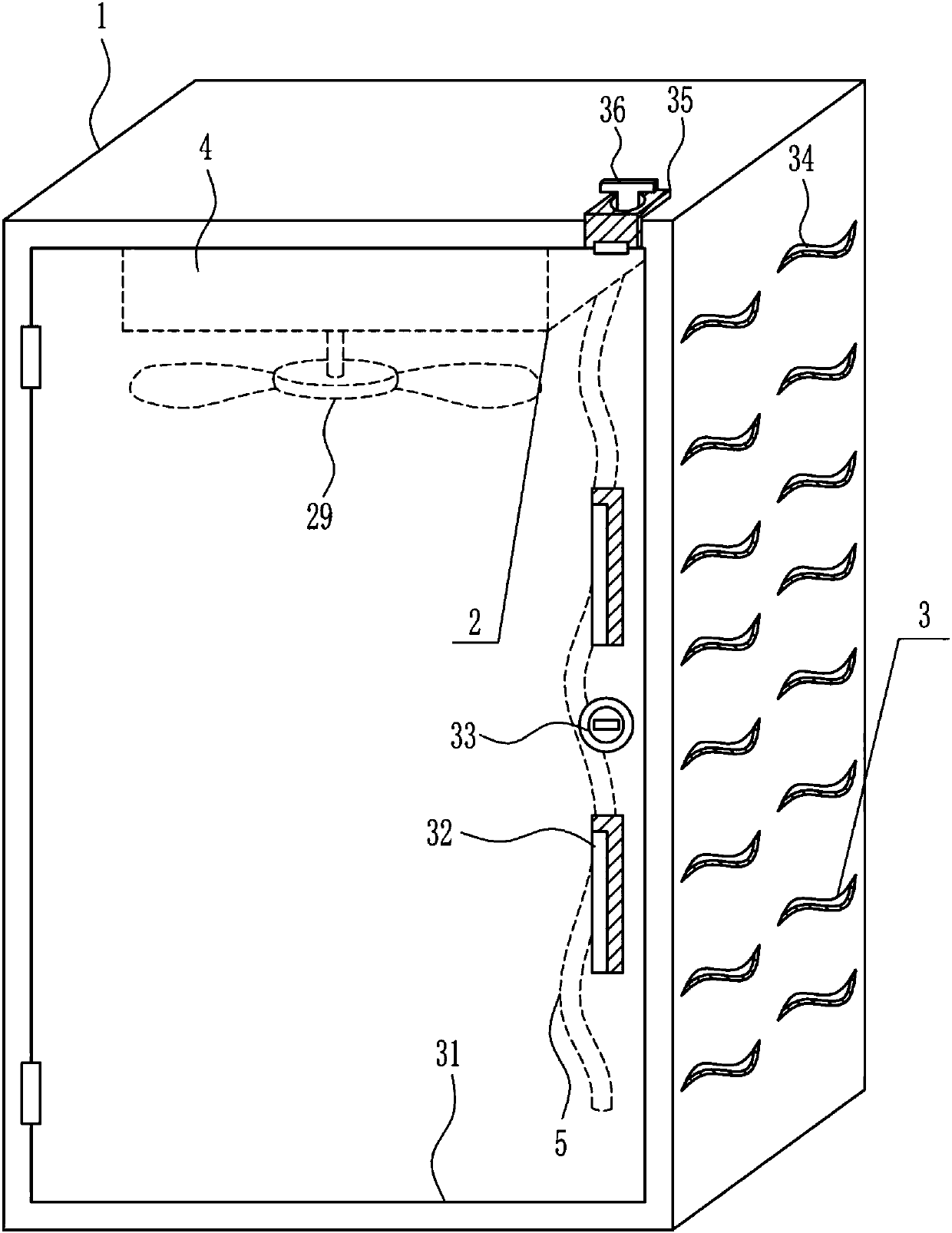
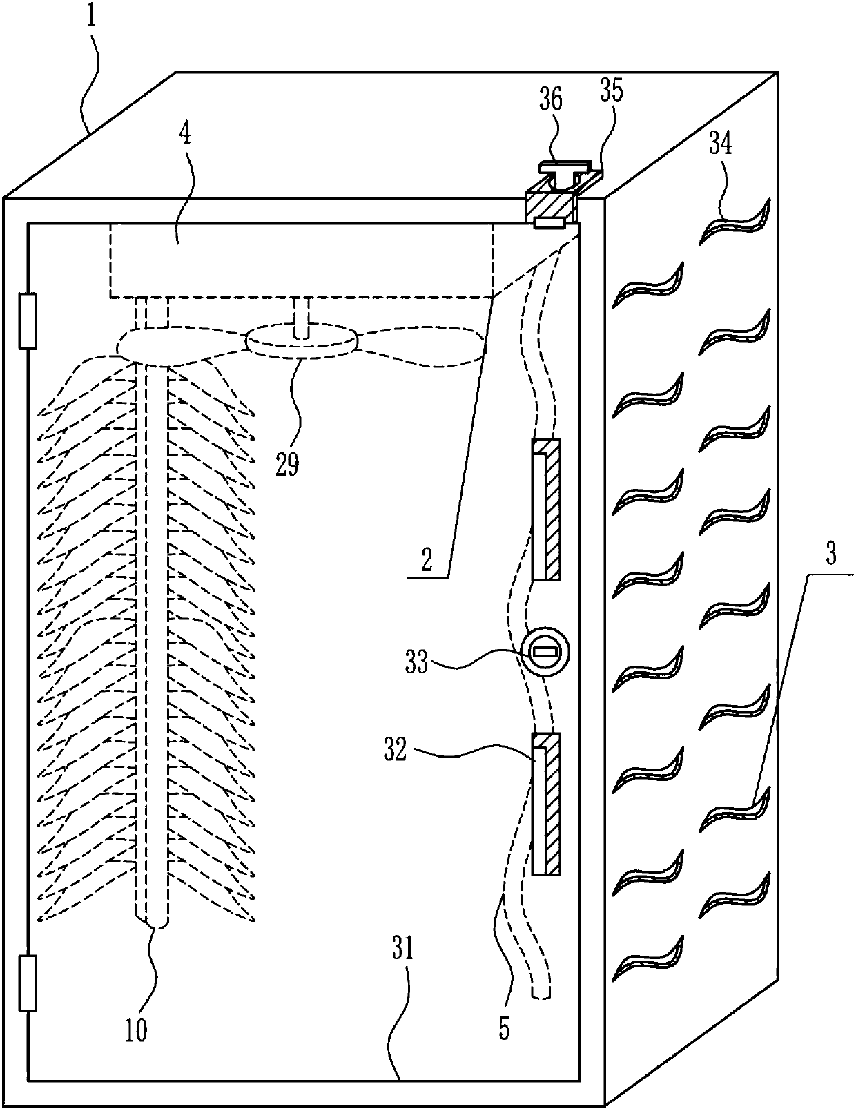
[0031] A heat dissipation switchgear with cleaning function, such as Figure 1-6 As shown, it includes a switchgear 1, a heat dissipation cleaning mechanism 2, a switchgear 3, an installation frame 4 and a cleaning strip 5. The switchgear 1 is provided with a switchgear 3 at the front, and the top of the switchgear 1 is connected with an installation frame 4. The installation frame 4 is provided with a heat dissipation cleaning mechanism 2, and a cleaning strip 5 is connected to the heat dissipation cleaning mechanism 2.

Embodiment 2

[0033] A heat dissipation switchgear with cleaning function, such as Figure 1-6 As shown, it includes a switchgear 1, a heat dissipation cleaning mechanism 2, a switchgear 3, an installation frame 4 and a cleaning strip 5. The switchgear 1 is provided with a switchgear 3 at the front, and the top of the switchgear 1 is connected with an installation frame 4. The installation frame 4 is provided with a heat dissipation cleaning mechanism 2, and a cleaning strip 5 is connected to the heat dissipation cleaning mechanism 2.

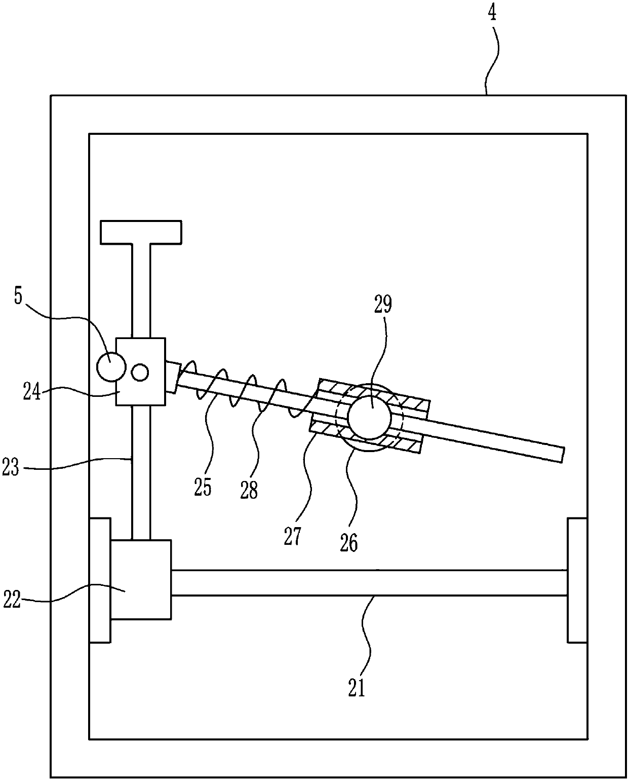
[0034] Radiation cleaning mechanism 2 comprises guide rail 21, guide sleeve 22, moving rod 23, moving block 24, rotating rod 25, motor 26, rotating block 27, first spring 28 and blade 29, between the left and right sides of installation frame 4 rear portions The guide rail 21 is connected between them, the guide rail 21 is provided with a guide sleeve 22, the guide rail 21 cooperates with the guide sleeve 22, the front end of the guide sleeve 22 is connected...

Embodiment 3

[0036] A heat dissipation switchgear with cleaning function, such as Figure 1-6 As shown, it includes a switchgear 1, a heat dissipation cleaning mechanism 2, a switchgear 3, an installation frame 4 and a cleaning strip 5. The switchgear 1 is provided with a switchgear 3 at the front, and the top of the switchgear 1 is connected with an installation frame 4. The installation frame 4 is provided with a heat dissipation cleaning mechanism 2, and a cleaning strip 5 is connected to the heat dissipation cleaning mechanism 2.

[0037] Radiation cleaning mechanism 2 comprises guide rail 21, guide sleeve 22, moving rod 23, moving block 24, rotating rod 25, motor 26, rotating block 27, first spring 28 and blade 29, between the left and right sides of installation frame 4 rear portions The guide rail 21 is connected between them, the guide rail 21 is provided with a guide sleeve 22, the guide rail 21 cooperates with the guide sleeve 22, the front end of the guide sleeve 22 is connected...


PUM


Abstract

The invention relates to a heat dissipation type switch cabinet, in particular to a heat dissipation type switch cabinet with a sweeping function. Heat can be dissipated at any time when a switch cabinet works, and the inside of the switch cabinet can be swept. The heat dissipation type switch cabinet with the sweeping function comprises the switch cabinet and the like. Switch mechanisms are arranged at the front of the switch cabinet, a mounting frame is connected with the inner top of the switch cabinet, a heat dissipation and sweeping mechanism is arranged in the mounting frame, and a sweeping strip is connected onto the heat dissipation and sweeping mechanism. The heat dissipation type switch cabinet has the advantages that the heat can be dissipated at any time when the switch cabinetworks, and the inside of the switch cabinet can be swept; the heat dissipation type switch cabinet is provided with the heat dissipation and sweeping mechanism, dust on the inner periphery of the switch cabinet can be swept by the sweeping strip, the heat can be dissipated for the switch cabinet by a blade, and accordingly effects of sweeping the switch cabinet and dissipating the heat can be realized.

Description

technical field [0001] The invention relates to a heat radiation switch cabinet, in particular to a heat radiation switch cabinet with a cleaning function. Background technique [0002] A switchgear is an electrical device that controls the on and off of various devices. The external line of the switch cabinet first enters the main control switch in the cabinet, and then enters the sub-control switch, and each branch is set according to its needs. Such as instruments, automatic controls, motor magnetic switches, various AC contactors, etc., some also have high-voltage room and low-voltage room switch cabinets, high-voltage busbars, such as power plants, etc. load shedding. The components in the switch cabinet mainly include circuit breakers, disconnectors, load switches, operating mechanisms, transformers and various protection devices. There are many classification methods of switch cabinets. For example, according to the installation method of circuit breakers, it can b...

Claims


Application Information

Patent Timeline
IPC IPC(8): H02B1/30H02B1/38H02B1/56H02B1/54H02B3/00
Inventor 徐美娣黎奕斌余国宁
Owner 南京永合电力科技有限公司
Why Eureka
Try Eureka