Optical keyboard

An optical and keyboard technology, applied in electrical components, electrical switches, circuits, etc., to solve problems such as inaccurate assembly, wrongly generated signals by keys, and impact on accuracy.

Inactive Publication Date: 2018-01-19
PRIMAX ELECTRONICS LTD
View PDF9 Cites 3 Cited by
  • Summary
  • Abstract
  • Description
  • Claims
  • Application Information

AI Technical Summary

Problems solved by technology

However, in the assembly structure of the existing keyboard 7, due to the existence of the spacer 76, the traditional keyboard 7 will have floating tolerances in assembly, resulting in inaccurate assembly.
On the other hand, external dust or liquid can easily enter the upper surface of the circuit board 73 through the opening 710, causing the keys to generate false signals and affecting the accuracy.

Method used


Image

  • Optical keyboard
  • Optical keyboard
  • Optical keyboard

Examples


Embodiment Construction

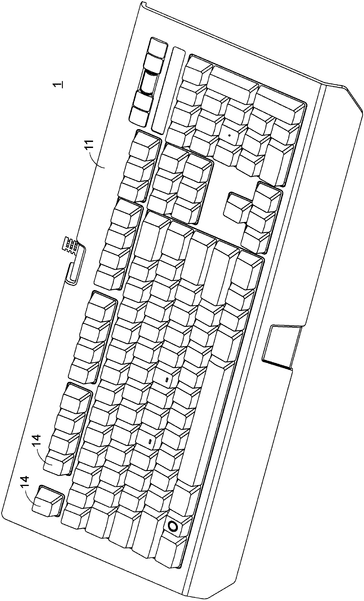
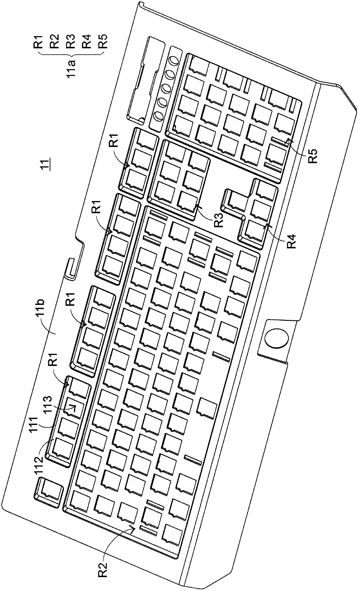
[0042] see figure 2 , figure 2 It is a three-dimensional schematic diagram of the optical keyboard of the present invention, image 3 It is a three-dimensional schematic diagram of the upper cover of the optical keyboard of the present invention, Figure 4 as well as Figure 5 It is an explosion schematic diagram of the optical keyboard of the present invention at different viewing angles. Firstly, each main element of the present invention will be briefly described. The optical keyboard 1 of the present invention includes an upper cover 11 , a bottom plate 12 , a circuit board 13 and a plurality of optical keys 14 . Such as figure 2 as well as image 3 As shown, the upper cover 11 is integrally formed, and includes at least one key area 11a and an edge area 11b. The key area 11a has a plurality of key openings 113 for the optical keys 14 to pass through.

[0043] Preferably, the upper cover 11 of the present invention includes a plurality of key areas 11a. The posi...


PUM


Abstract

The invention provides an optical keyboard which comprises an upper cover, a bottom board, a circuit board and a plurality of optical keys. The circuit board is disposed between the upper cover and the bottom board, and is upwardly abutted against the upper cover. Each of the keys is disposed in a plurality of key openings of the cover so that the bottom surface of each of the keys can be abuttedagainst the upper surface of the circuit board. The upper cover is an integrally-formed structure, thereby simplifying the arrangement of the components of the optical keyboard and making assembly accurate.

Description

technical field [0001] The invention relates to an optical keyboard, in particular to an optical keyboard with a simpler assembly structure. Background technique [0002] A keyboard is an indispensable device for modern people to use a computer. Many keys are arranged on the keyboard for users to press to input commands. [0003] see figure 1 , the traditional keyboard 7 includes an upper cover 71 , a middle frame metal plate 72 , a circuit board 73 , a plurality of keys 74 and a bottom plate 75 . A plurality of buttons 74 are first positioned on the circuit board 73 with the help of the middle frame metal plate 72, and then because the upper surface of the upper cover 71 presents a slope, the circuit board 73 is assembled to the bottom plate 75 through a spacer 76, thereby , so that when the upper cover 71 is assembled to the bottom plate 75 , the button 74 passes through an opening 710 of the upper cover 71 , and the height of the button 74 can be set according to the s...

Claims


Application Information

Patent Timeline
Patent Type & Authority Applications(China)
IPC IPC(8): H01H13/704H01H13/7065H01H13/86
Inventor 张家源萧绍崙
Owner PRIMAX ELECTRONICS LTD
Why Eureka
Try Eureka