
Three-dimensional synthetic aperture radar imaging method based on electromagnetic vortex waves

A technology of synthetic aperture radar and imaging method, which can be used in the reflection/re-radiation of radio waves, radio wave measurement systems, and the use of re-radiation, etc., and can solve the problems of influence and increase in the number of array elements.

Active Publication Date: 2018-01-19
UNIV OF ELECTRONICS SCI & TECH OF CHINA
View PDF4 Cites 10 Cited by
  • Summary
  • Abstract
  • Description
  • Claims
  • Application Information

AI Technical Summary

Problems solved by technology

However, there are two main problems in the downward line-of-sight linear array 3D SAR: the vertical heading resolution is affected by the size of the array, which is usually lower than the resolution along the heading and range; to avoid blurred images, the array elements in the vertical heading The spacing must be small enough to result in a large increase in the number of elements
However, the current research is limited to the fact that the radar and the target are relatively stationary, and only two-dimensional images of the target can be obtained.

Method used


Image

  • Three-dimensional synthetic aperture radar imaging method based on electromagnetic vortex waves
  • Three-dimensional synthetic aperture radar imaging method based on electromagnetic vortex waves
  • Three-dimensional synthetic aperture radar imaging method based on electromagnetic vortex waves

Examples


Embodiment Construction

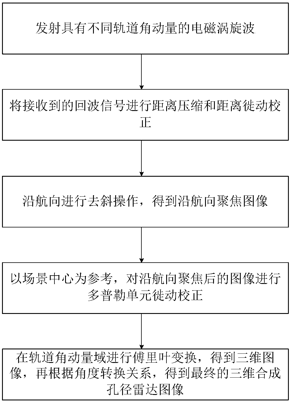
[0018] Refer to attached figure 1 , the specific implementation steps of the present invention are as follows:

[0019] Step 1, emitting electromagnetic vortex waves with different OAM states.

[0020] There are several ways of OAM generation and emission at present. The present invention takes the uniform circular array as an example. After proper radiation waveform adjustment, the chirp signal emitted by the nth array element is

[0021]

[0022] Among them, τ represents the fast distance time, l is the number of OAM modes, A l is the signal amplitude of the emitted OAM state l, N l The number of array elements required to generate a signal with OAM state l, w r is the distance envelope, f c is the carrier frequency, γ r is the distance chirp frequency, is the modulation phase of the nth array element.

[0023] Step 2, performing range compression and range migration correction on the received echo signal.

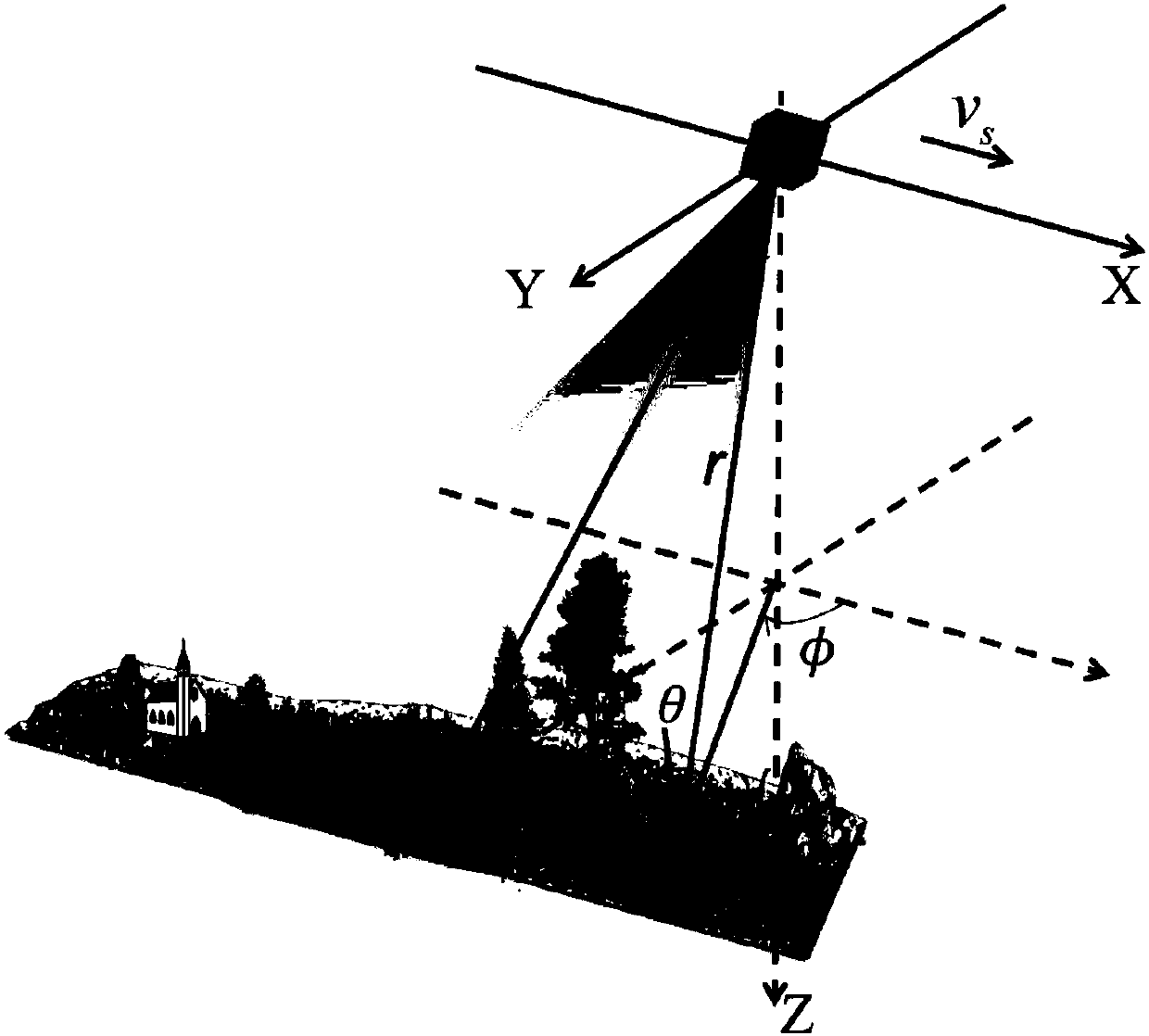
[0024] A schematic diagram of the imaging geometry of t...


PUM


Abstract

The invention discloses a three-dimensional synthetic aperture radar imaging method based on electromagnetic vortex waves. The method mainly solves the problem that according to existing two-dimensional imaging methods, only relative stillness of an object and a radar is taken into consideration. The method comprises the steps that 1, the electromagnetic vortex waves with different orbital angularmomentum are emitted; 2, range compression and range migration correction are conducted on received echo signals; 3, deramping operation is conducted in the heading direction to obtain a focus imagein the heading direction; 4, the scene center is regarded as reference, and Doppler cell migration correction is conducted on the focused image in the heading direction; 5, Fourier transformation is conducted in an orbital angular momentum field to obtain a three-dimensional image, and then according to angle transformation relations, a final three-dimensional synthetic aperture radar image is obtained. According to the method, by means of the orbital angular momentum carried by the electromagnetic vortex waves in combination with relative motions of the object and the radar, three-dimensionalsynthetic aperture radar imaging is achieved.

Description

technical field [0001] The invention belongs to the technical field of radar, and further relates to a synthetic aperture radar (Synthetic Aperture Radar, SAR) three-dimensional imaging method in the technical field of radar imaging. Background technique [0002] Synthetic aperture radar has been widely used in military and civilian fields such as strategic defense and terrain surveying and mapping because of its all-day, all-weather, and long-range imaging capabilities. Traditional SAR can only acquire two-dimensional images on an oblique plane, and is affected by overlap and perspective shrinkage. In order to overcome the defects of two-dimensional imaging, scholars at home and abroad have proposed a variety of three-dimensional SAR imaging methods. At present, 3D SAR imaging has become one of the research hotspots of modern radar. [0003] As one of the main technologies to realize 3D SAR imaging, the downward line-of-sight linear array 3D SAR system has attracted the a...

Claims


Application Information

Patent Timeline
Patent Type & Authority Applications(China)
IPC IPC(8): G01S13/90
Inventor 杨桃丽淦小健王勇
Owner UNIV OF ELECTRONICS SCI & TECH OF CHINA
Learn More