
3D glass forming die structure

A glass forming and 3D technology, which is applied in glass forming, glass reshaping, glass manufacturing equipment, etc., can solve the problems of insufficient precision control, large product eccentricity, and high product defective rate, so as to improve smoothness, Effect of improving heating efficiency and reducing warpage

Inactive Publication Date: 2018-01-19
湖北天宝光电科技有限公司
View PDF5 Cites 0 Cited by
  • Summary
  • Abstract
  • Description
  • Claims
  • Application Information

AI Technical Summary

Problems solved by technology

[0005] In order to overcome the problems of large eccentricity of products produced by product 3D glass forming molds in the prior art, insufficient precision control, high product defective rate, etc., the present invention provides a structure of 3D glass forming molds, including upper and lower convex molds and concave molds. The 3D glass is sandwiched between the male mold and the concave mold, and the convex mold is provided with two grooves parallel to the sides of the 3D glass and located on both sides of the 3D glass. There are clamping angles corresponding to the two grooves on the mold, and the inside of the grooves is provided with a limit step with a vertical distance of 0.03-0.05mm from the highest point on the left / right side of the 3D glass

Method used


Image

  • 3D glass forming die structure
  • 3D glass forming die structure
  • 3D glass forming die structure

Examples


Embodiment Construction

[0038] The present invention will be described in further detail below in conjunction with the accompanying drawings and embodiments. It should be understood that the specific embodiments described here are only used to explain the present invention, not to limit the present invention.

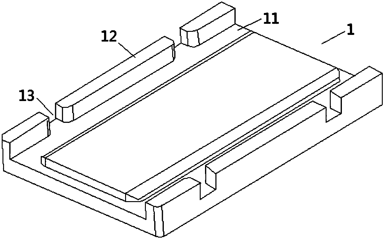
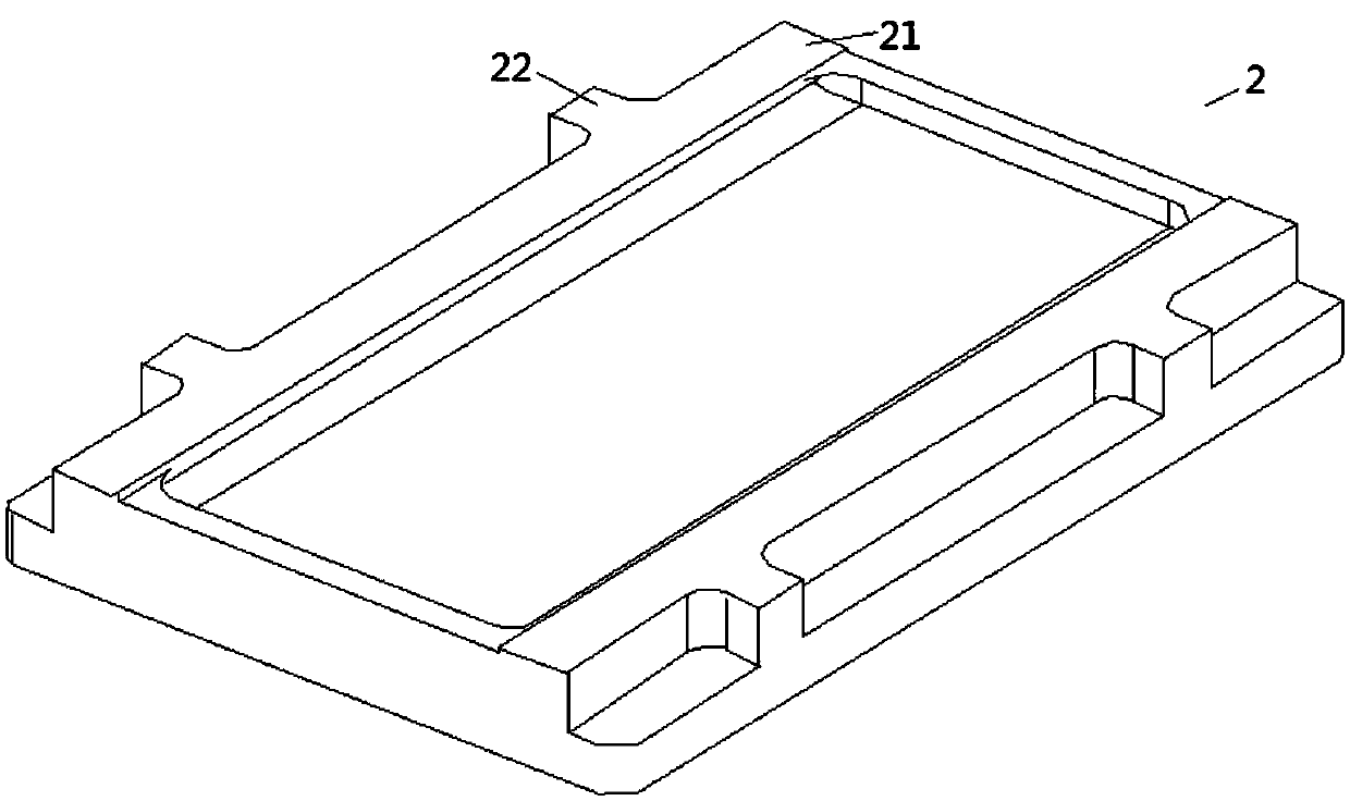
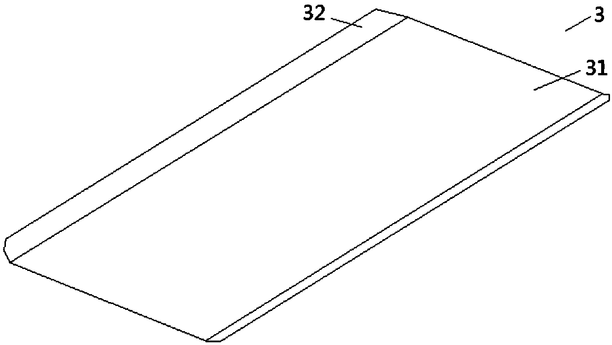
[0039] Such as Figure 1-4 As shown, the 3D glass forming mold structure includes a convex mold 1 and a concave mold 2 arranged up and down, the 3D glass 3 is sandwiched between the convex mold 1 and the concave mold 2, and the convex mold 1 is provided with two The sides of the 3D glass 3 are parallel to the grooves 11 located on both sides of the 3D glass 3, and the concave mold 2 is provided with corners 21 corresponding to the two grooves 11, and the 3D glass 3 includes The main body part 31 and the curved surface parts 32 arranged on both sides of the main body part.

[0040] Two locking edges 12 parallel to the groove 11 are arranged on both sides of the punch 1, and more than one lock...


PUM


Abstract

The invention discloses a 3D glass forming die structure and belongs to the field of dies. The 3D glass forming die structure comprises a male die and a female die which are vertically arranged, wherein 3D glass is sandwiched between the male die and the female die; two grooves which are parallel to the side edge of the 3D glass and positioned on two sides of the 3D glass are formed in the male die; clamping angles corresponding to the two grooves are formed in the female die; limiting steps which are 0.03-0.05mm away from the highest point on a left / right side face of the 3D glass in the vertical direction are formed inside the grooves. The 3D glass forming die structure disclosed by the invention has the beneficial effects that the limiting steps are formed inside the grooves, so that the limiting steps can achieve effects of limiting two side edges of the glass so as to prevent the glass from swinging from side to side; however, since the glass is expanded while heated, the distancebetween the step plane and the highest point on a left / right side face of the 3D glass in the vertical direction is 0.03-0.05mm, imprint or debris appearing on the glass edges can be avoided.

Description

technical field [0001] The invention relates to the field of molds, in particular to a 3D glass forming mold structure. Background technique [0002] With the rise of 3D curved screens and the 5G era of communication, more and more smartphones use 3D curved glass (front and rear covers). The 5G era will completely abandon the existing metal back cover and use glass materials that will not shield signals. [0003] In the molding process of 3D curved glass, the contour of glass molding is very important to control precision for 3D curved surfaces. Once the glass is off-centered during the molding process, the glass contour will deviate to one side, and the accuracy cannot be guaranteed. All for 3D curved surfaces The eccentric control of glass is particularly important; at present, there are very few studies on eccentric control of 3D curved glass. For example, the utility model patent with the notification number CN2601253Y discloses a microcrystalline glass substrate blank f...

Claims


Application Information

Patent Timeline
IPC IPC(8): C03B23/03C22C29/12C22C30/06
Inventor 黎锦林
Owner 湖北天宝光电科技有限公司
Learn More