
Automatic plate machining system

A sheet metal processing, one-to-one technology, applied in metal processing equipment, manufacturing tools, other manufacturing equipment/tools, etc., can solve the problems of increased operator safety hazards, high manual labor intensity, and inconvenient manual transfer, etc., to achieve labor intensity. No potential safety hazards, low labor intensity, and short working cycle

Active Publication Date: 2018-01-19
江苏扬力数控机床有限公司
View PDF9 Cites 18 Cited by
  • Summary
  • Abstract
  • Description
  • Claims
  • Application Information

AI Technical Summary

Problems solved by technology

[0002] At present, the plate processing equipment is mainly composed of laser cutting and bending. When people operate, they usually use manual or small carts to transfer the plates between the equipment and the equipment and the warehouse. Extremely low efficiency, long processing cycle and high labor intensity
At the same time, if the plate to be processed is thick, the corresponding weight is relatively large, and manual transfer is extremely inconvenient; and if the plate to be processed is thin, its edges will be relatively sharp, which brings great safety hazards to operators. increase

Method used


Image

  • Automatic plate machining system
  • Automatic plate machining system
  • Automatic plate machining system

Examples


Embodiment Construction

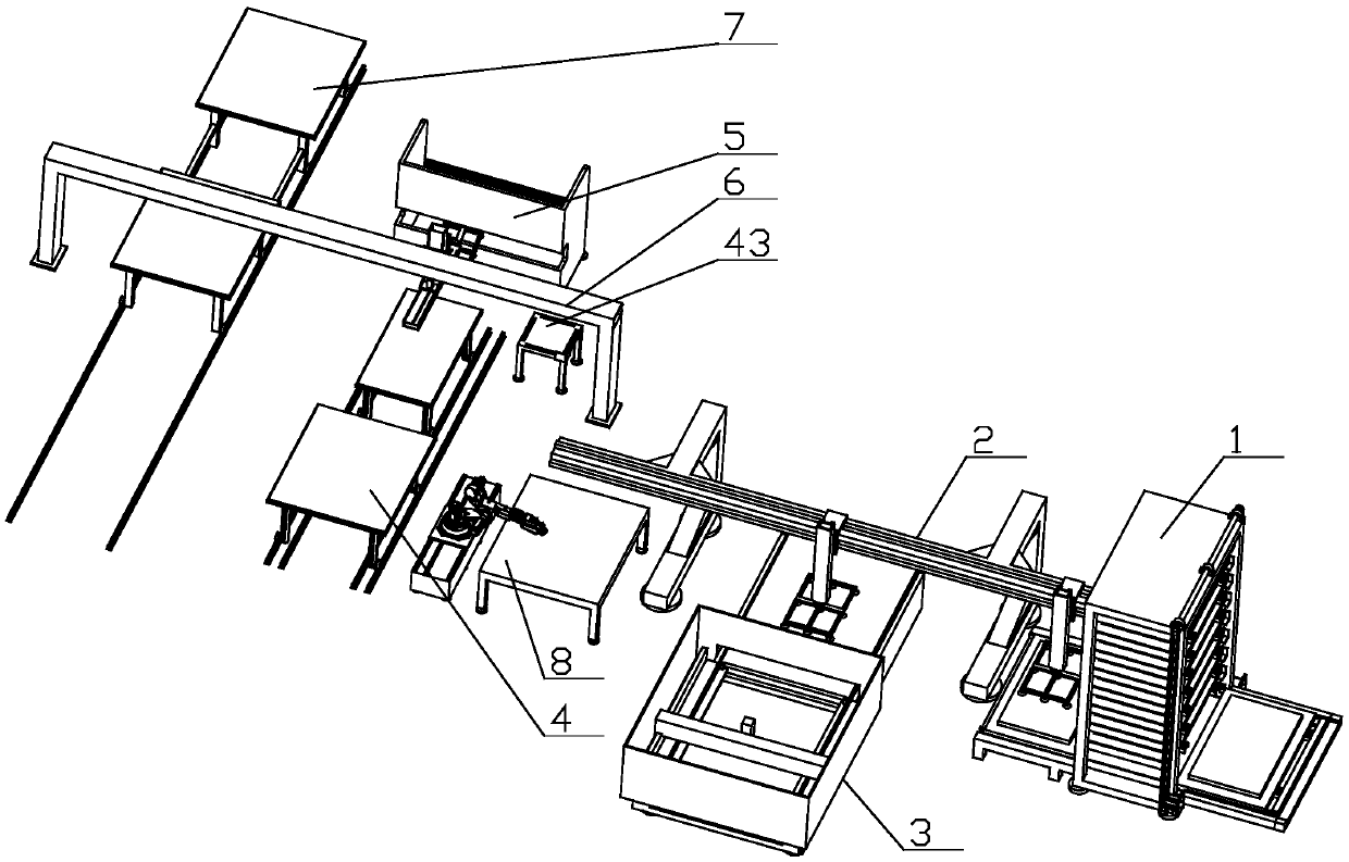
[0067] The present invention as Figure 1-27 As shown, it includes silo 1, translation manipulator assembly 2, laser cutting assembly 3, double-layer movable material table 4, bending machine 5, transfer manipulator assembly 6 and stacking table 7;

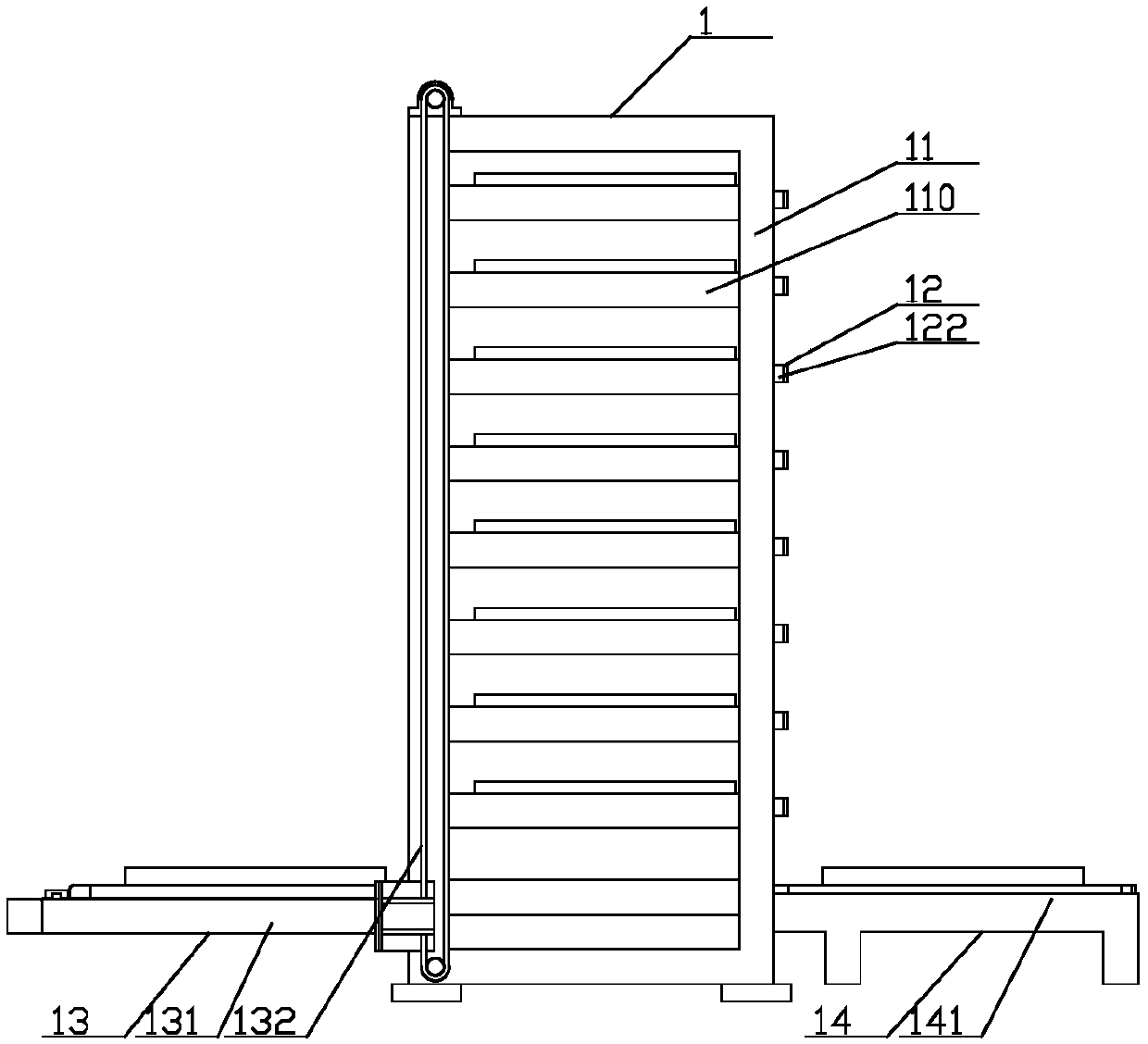
[0068] The silo 1 includes a storage rack 11, a number of support plates 12 (for supporting and storing plates 9), a support plate lifting assembly 13 and a support plate translation assembly 14, and the two sides of the storage rack 11 Several pairs of supporting bars 110 are fixedly connected on the inner wall, and several pairs of supporting bars 110 are evenly distributed from top to bottom, and both sides of the supporting plate 12 are slidingly connected on the same pair of supporting bars 110; (wherein the bottom layer The support strips are only used for the transfer of the pallets, not for the storage of the pallets)

[0069] The supporting plate lifting assembly 13 includes a lifting platform 131, a lifting platform dri...


PUM


Abstract

The invention discloses an automatic plate machining system, relates to the field of plate machining equipment, and particularly relates to an improvement of an assembly line for step-by-step machining of plates. According to the automatic plate machining system, the structure is ingenious, the working efficiency is high, the machining period is short and the stability is good, and continuous andhighly-automatic plate machining can be realized by utilizing manual remote control in the using process. The automatic plate machining system comprises a stock bin, a horizontal moving mechanical armassembly, a laser cutting assembly, a double-layer movable material table, a bending machine, a transferring mechanical arm assembly and stacking workbenches; and the stock bin comprises a material storage frame, a plurality of bearing plates, a bearing plate lifting assembly and a bearing plate horizontal moving assembly, a plurality pairs of bearing strips are fixedly connected to the inner walls of the two sides of the material storage frame, the plurality pairs of bearing strips are uniformly distributed from top to bottom, and the two sides of each bearing plate are connected to the samecorresponding pair of bearing strips in a sliding mode. The automatic plate machining system of the technical scheme on the whole has the advantages of being capable of achieving continuous work, high in working efficiency, short in working period, high in automation degree, low in labor intensity and free of potential safety hazards.

Description

technical field [0001] The invention relates to the field of sheet material processing equipment, in particular to the improvement of an assembly line for step-by-step processing of sheet materials. Background technique [0002] At present, the plate processing equipment is mainly composed of laser cutting and bending. When people operate, they usually use manual or small carts to transfer the plates between the equipment and the equipment and the warehouse. The efficiency is extremely low, the processing cycle is long and the labor intensity is high. At the same time, if the plate to be processed is thick, the corresponding weight is relatively large, and manual transfer is extremely inconvenient; and if the plate to be processed is thin, its edges will be relatively sharp, which brings great safety hazards to operators. increase. Contents of the invention [0003] Aiming at the above problems, the present invention proposes an automatic sheet metal processing system wi...

Claims


Application Information

Patent Timeline
Patent Type & Authority Applications(China)
IPC IPC(8): B23K26/00B23P23/00
Inventor 潘志华胡金龙陈亮陈龙吴东升
Owner 江苏扬力数控机床有限公司
Learn More