Dust removal orifice building floor tiles

A technology for dust removal holes and floor tiles, which is applied in the field of building decoration materials, can solve problems such as inconvenience and hidden dangers, messiness, and hidden dangers, and achieve the effects of preventing the spread of dirt, protecting cleanliness, and quickly draining water.

Active Publication Date: 2019-12-31
尹红文
View PDF5 Cites 0 Cited by
  • Summary
  • Abstract
  • Description
  • Claims
  • Application Information

AI Technical Summary

Problems solved by technology

[0002] Floor tiles are an extremely important building material in interior construction and decoration. The surface of floor tiles is smooth and smooth, which can have a good water-proof effect; the smooth surface makes the ground smooth and clean, which can effectively improve the style of interior decoration. , the configuration and pattern of floor tiles can effectively reveal the preferences and characteristics of the room owner, or provide a comfortable visual environment for viewing customers; however, because the surface of the floor tiles is too smooth, fine dust can be highlighted, if If it cannot be cleaned in time, the whole floor will look dirty; in addition, the water stains left by mopping the floor and the oil stains left by food will cause the surface of the floor tiles to be very slippery, and customers and residents are very easy to fall when walking , there is a great potential safety hazard; especially in rainy days, the clean shopping mall will be polluted by messy footprints, and the slippery shopping mall will also bring a lot of inconvenience to customers; in summary, although the existing floor tiles are clean and beautiful , but it is difficult to take care of, and there are many inconveniences and safety hazards when walking and using

Method used


Image

  • Dust removal orifice building floor tiles
  • Dust removal orifice building floor tiles
  • Dust removal orifice building floor tiles

Examples


Embodiment

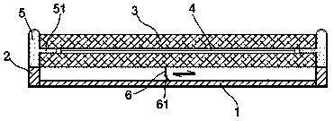
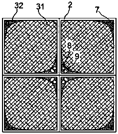
[0023] exist Figure 1 to Figure 3 In the shown embodiment, the dust-removing orifice building floor tile includes a base plate 1, a hollow surrounding edge 2 is fixedly arranged on the four sides of the base plate 1, and two layers of bearing plates 3 are arranged parallelly above the base plate 1, so that The bearing plate 3 includes a rhombus-shaped hard net plate 31, and the four corners of the hard net plate 31 are integrally provided with reinforcing angles 32; The upper edge of the surrounding edge 2 is flush; the space between the carrier plate 3 and the base plate 1 is suspended;

[0024] A cutting mesh 4 is arranged in the gap between the two layers of the carrying plate 3, and the cutting mesh 4 can freely translate along the surface of the carrying plate 3;

[0025] An annular regulating bag 5 is installed in the hollow area of ​​the surrounding edge 2, and the regulating liquid is filled in the regulating bag 5; the upper ring edge of the regulating bag 5 is expo...


PUM


Abstract

The invention relates to a dust removing hole plate building floor tile. The dust removing hole plate building floor tile comprises a substrate; surrounding edges are arranged on the substrate; bearing plates are arranged above the substrate, and the space between the bearing plates and the substrate is suspended; a cutting net piece is arranged in a gap between every two layers of bearing plates;an adjusting bag is installed in the surrounding edges; adjusting columns are arranged on the side annular face of the adjusting bag at equal intervals, and the adjusting columns are fixedly connected with the cutting net pieces; cleaning scraper blades are arranged between the substrate and the bearing plates; a resetting shaft and an adjusting shaft are arranged on two skew diagonals of the floor tile; the resetting shaft is sleeved with a resetting coil spring; the adjusting shaft is sleeved with an adjusting ring; the resetting coil spring is connected with the back side of each cleaningscraper blade through a resetting rope, and the adjusting ring is connected with the front side of each cleaning scraper blade through an adjusting rope; and a sucking hole is further formed tightly close to the adjusting shaft. The floor tile is exquisite in structure and capable of efficiently removing dust and draining water, keeps the ground clean, improves the style of building decoration, and guarantees the travelling safety and stability.

Description

technical field [0001] The invention relates to a building decoration material, in particular to a floor tile. Background technique [0002] Floor tiles are an extremely important building material in interior construction and decoration. The surface of floor tiles is smooth and smooth, which can have a good water-proof effect; the smooth surface makes the ground smooth and clean, which can effectively improve the style of interior decoration. , the configuration and pattern of floor tiles can effectively reveal the preferences and characteristics of the room owner, or provide a comfortable visual environment for viewing customers; however, because the surface of the floor tiles is too smooth, fine dust can be highlighted, if If it cannot be cleaned in time, the whole floor will look dirty; in addition, the water stains left by mopping the floor and the oil stains left by food will cause the surface of the floor tiles to be very slippery, and customers and residents are very...

Claims


Application Information

Patent Timeline
Patent Type & Authority Patents(China)
IPC IPC(8): E04F19/10
Inventor 尹红文白晶仲杏英
Owner 尹红文
Why Eureka
Try Eureka