Vibrating tamper for hydraulic engineering

A technology of hydraulic engineering and vibratory rammer, applied in the field of vibratory rammer, can solve problems such as mechanical damage, and achieve the effect of reducing the impact

Inactive Publication Date: 2018-01-16
邰学兰
View PDF0 Cites 2 Cited by
  • Summary
  • Abstract
  • Description
  • Claims
  • Application Information

AI Technical Summary

Problems solved by technology

[0003] The current vibratory rammers rarely have vibration reduction treatment, which has certain damage to the machinery, so we need a vibratory rammer for water conservancy projects to solve the above problems and meet people's needs

Method used


Image

  • Vibrating tamper for hydraulic engineering
  • Vibrating tamper for hydraulic engineering
  • Vibrating tamper for hydraulic engineering

Examples


Embodiment Construction

[0018] The following will clearly and completely describe the technical solutions in the embodiments of the present invention with reference to the accompanying drawings in the embodiments of the present invention. Obviously, the described embodiments are only some, not all, embodiments of the present invention. Based on the embodiments of the present invention, all other embodiments obtained by persons of ordinary skill in the art without making creative efforts belong to the protection scope of the present invention.

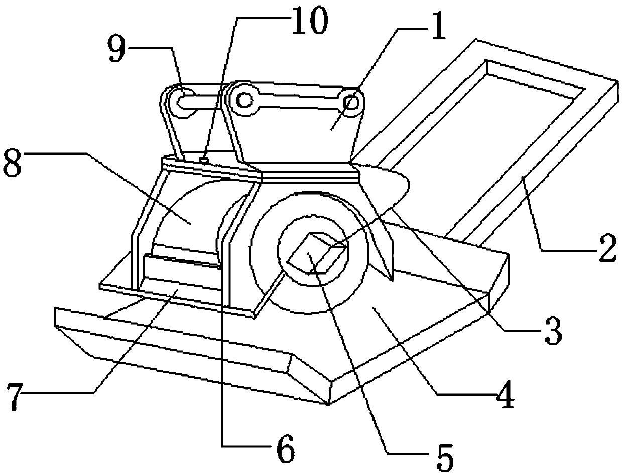
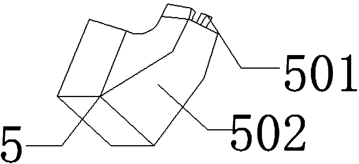
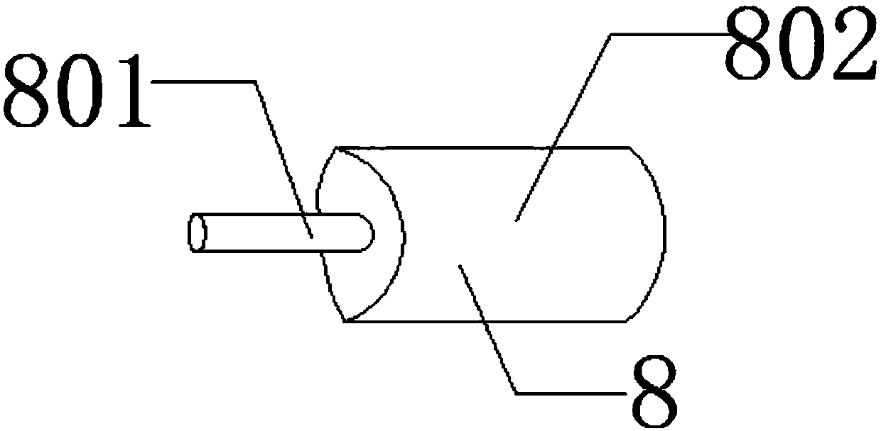
[0019] The present invention provides such figure 1 , figure 2 with image 3 A vibrating rammer for water conservancy projects shown includes a hydraulic motor 8, an eccentric vibrator 6 is provided on the right side of the hydraulic motor 8, and a rubber damping block 5 is provided on the right side of the eccentric vibrator 6, and the rubber damping block 5 is provided on the right side of the eccentric vibrator 6. The front of the vibration block 5 is pr...


PUM


Abstract

The invention discloses a vibrating tamper for hydraulic engineering. The vibrating tamper comprises a hydraulic motor, wherein an eccentric vibrator is arranged on the right side of the hydraulic motor; a rubber damping block is arranged on the right side of the eccentric vibrator; a power transmission rubber wire is arranged on the front side of the rubber damping block; a pushing handrail is arranged on the rear side of the power transmission rubber wire; a dustproof plate is arranged on the rear side of the hydraulic motor; a bottom tamping plate is arranged at the bottom of the dustproofplate; an operation button is arranged at the top of the hydraulic motor; a connecting support frame is arranged on the right side of the operation button; a mechanical receiving slot is formed on thefront side of the connecting support frame. The vibrating tamper for hydraulic engineering has a simple structure and practical functions and can meet the practical requirement of the water industryfor the vibration tamping.

Description

technical field [0001] The invention belongs to the technical field of vibratory rammers, and in particular relates to a vibratory rammer for water conservancy projects. Background technique [0002] Vibratory rammers are divided into internal combustion and electric vibratory plate compactors. The plate compactor model consists of two parts: class, group, type, characteristic code and main parameter code. The update code of the plate compactor is placed at the end of the plate compactor model. Vibratory plate compaction is mainly suitable for compacting materials with small cohesion and friction between particles, such as river sand, gravel and asphalt. The main working parameters of the vibratory plate compactor are: the area of ​​the bottom surface of the working plate, the mass of the whole machine, the exciting force and the exciting frequency. In general, the floor area of ​​the flat plate of the same specification is almost the same, so the performance of the flat r...

Claims


Application Information

Patent Timeline
Patent Type & Authority Applications(China)
IPC IPC(8): E02D3/074
Inventor 邰学兰
Owner 邰学兰
Why Eureka
Try Eureka