Multi-rotor unmanned aerial vehicle with lifting wing-like undercarriages

A multi-rotor UAV and landing gear technology, which is applied to landing gear, motor vehicles, aircraft parts, etc., can solve the problems of increasing the take-off weight of the aircraft, affecting the flight efficiency, and reducing the flight efficiency, so as to achieve small space occupation and improve flight efficiency. The effect of improving efficiency and flight efficiency

Pending Publication Date: 2018-01-16
TIANXUN INNOVATION BEIJING TECH CO LTD
View PDF5 Cites 6 Cited by
  • Summary
  • Abstract
  • Description
  • Claims
  • Application Information

AI Technical Summary

Problems solved by technology

As the load of the aircraft, the traditional landing gear has no function after being stowed except for take-off and landing. It only increases the take-off weight of the aircraft and reduces the flight efficiency.
The traditional UAV landing gear is composed of simple carbon tubes or carbon plates. It has no lift structure, the appearance is not beautiful, and it will generate waste resistance during the flight, which will affect the flight efficiency.
During the flight, the landing gear has no effect after being retracted, and it is a burden on the aircraft. If you want to improve performance, you can only reduce the weight of the landing gear as much as possible, and the size of the airframe itself limits the weight of the landing gear, so no matter what can't avoid this problem

Method used


Image

  • Multi-rotor unmanned aerial vehicle with lifting wing-like undercarriages
  • Multi-rotor unmanned aerial vehicle with lifting wing-like undercarriages
  • Multi-rotor unmanned aerial vehicle with lifting wing-like undercarriages

Examples


Embodiment Construction

[0019] The present invention is described in further detail now in conjunction with accompanying drawing. These drawings are all simplified schematic diagrams, which only illustrate the basic structure of the present invention in a schematic manner, so they only show the configurations related to the present invention.

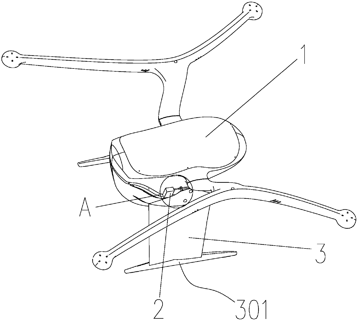
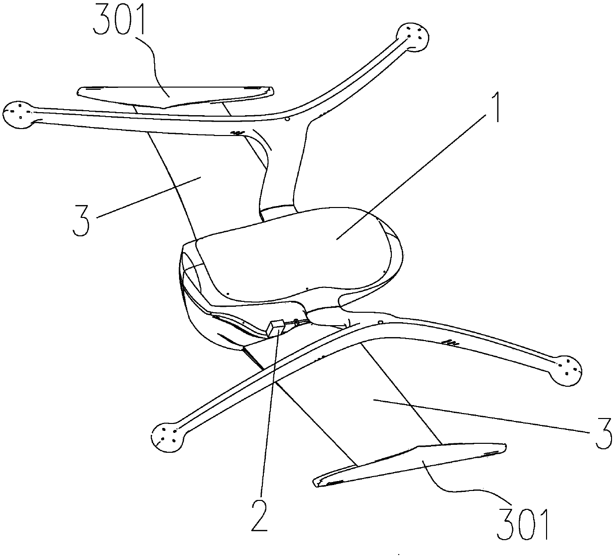
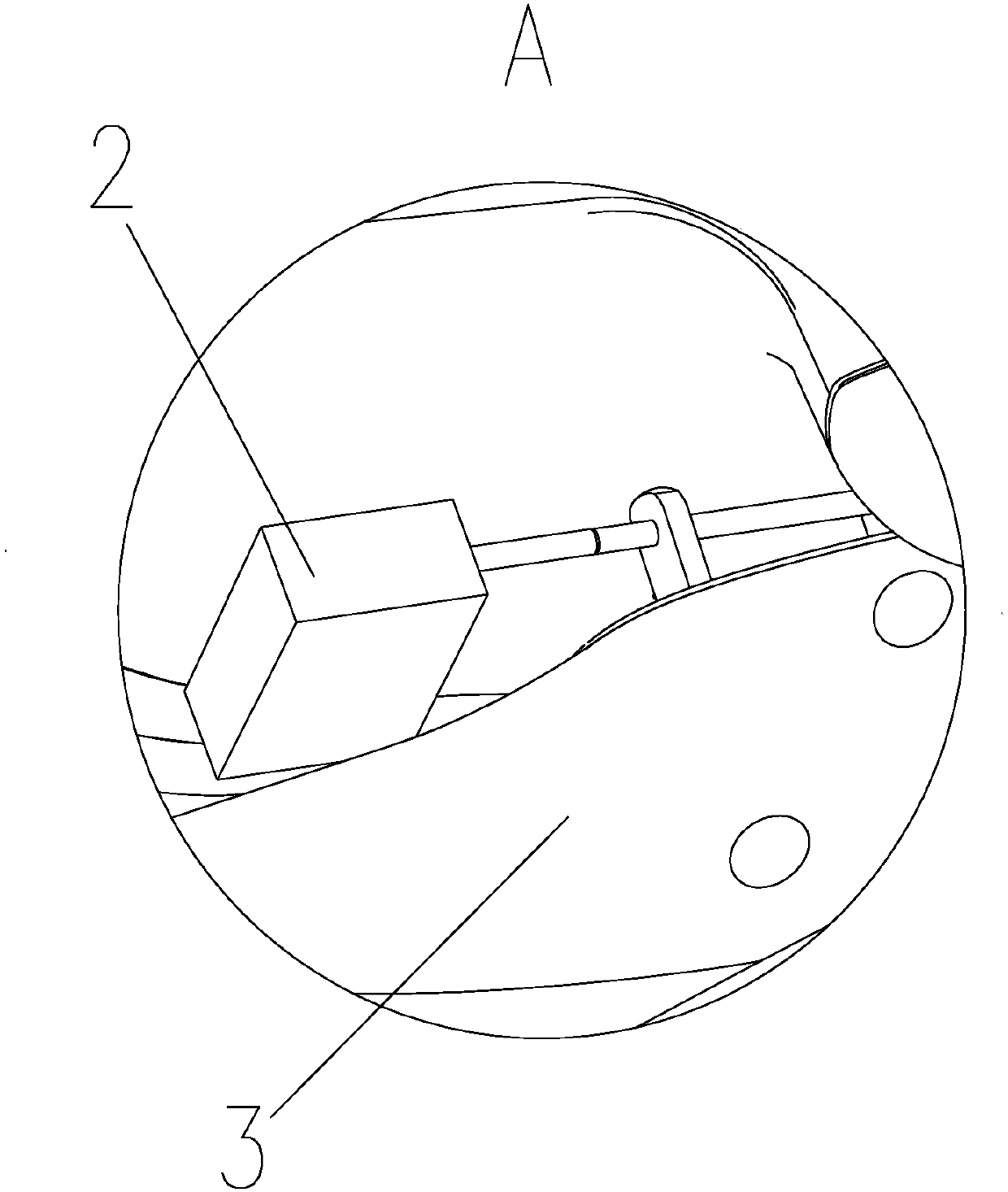
[0020] Such as Figure 1-Figure 5 Shown is a specific embodiment of a multi-rotor unmanned aerial vehicle with a lifting airfoil under the landing gear of the present invention, which includes a casing 1, and steering gears 2 are fixedly installed on both sides of the casing 1, and each steering gear 2 The central axes of the output shafts are all parallel to the forward direction of the multi-rotor UAV, and the output shafts of each steering gear 2 are fixedly connected with wing-shaped landing gear 3, and the central axes of the output shafts of each steering gear 2 are parallel On the airfoil of airfoil landing gear 3.

[0021] The airfoil landing gear 3 ...


PUM


Abstract

The invention specifically relates to a multi-rotor unmanned aerial vehicle with lifting wing-like undercarriages, belonging to the field of unmanned aerial vehicles. The multi-rotor unmanned aerial vehicle comprises a shell, wherein two sides of the shell are both fixedly provided with steering engines; the output shafts of the steering engines are parallel to the advancing direction of the unmanned aerial vehicle and are fixedly connected with the wing-like undercarriages; and the output shafts of the steering engines are parallel to the aerofoils of the wing-like undercarriages. The invention has the beneficial effects that air current can support the wing-like undercarriages when the multi-rotor unmanned aerial vehicle is flying forward, so lifting force is improved, and the cruising ability of the multi-rotor unmanned aerial vehicle is improved; the wing-like undercarriages employ a bionic design, conventional undercarriages producing ineffective resistance during flight and increasing weight are optimized into wing-like undercarriages capable of providing lifting force, so the flight efficiency of the multi-rotor unmanned aerial vehicle is enhanced; the wing-like undercarriages are no longer the burden of the unmanned aerial vehicle and can also providing lifting force like wings during flying of the unmanned aerial vehicle; and the wing-like undercarriages can be foldedand stored, and is smaller in occupied space and resistance and higher in reliability during flight.

Description

technical field [0001] The invention belongs to the field of unmanned aerial vehicle machinery, and in particular relates to a multi-rotor unmanned aerial vehicle whose landing gear has a lifting airfoil. Background technique [0002] Landing gear is an accessory device used to support the aircraft and move on the ground (water surface) when the lower part of the aircraft is used for take-off and landing or ground (water surface) taxiing. The landing gear is the only part that supports the entire aircraft, so it is an integral part of the aircraft; without it, the aircraft cannot move on the ground. After the aircraft takes off, the landing gear can be retracted depending on the flight performance. As the load of the aircraft, the traditional landing gear has no function after being stowed except for take-off and landing. It only increases the take-off weight of the aircraft and reduces the flight efficiency. The traditional UAV landing gear is composed of simple carbon tu...

Claims


Application Information

Patent Timeline
Patent Type & Authority Applications(China)
IPC IPC(8): B64C39/02B64C25/32B64C25/12
Inventor 王川谢茂彬
Owner TIANXUN INNOVATION BEIJING TECH CO LTD
Why Eureka
Try Eureka