
Electric lifting device for high-voltage transmission line tower working

A technology of high-voltage transmission lines and lifting devices, which is applied in the direction of lifting devices, overhead lines/cable equipment, etc., can solve problems such as high labor intensity, power outage accidents, electric shock injuries, etc., to reduce labor intensity, prevent unsafe behaviors, and improve The effect of safe operation

Active Publication Date: 2018-01-12
宋磐
View PDF5 Cites 2 Cited by
  • Summary
  • Abstract
  • Description
  • Claims
  • Application Information

AI Technical Summary

Problems solved by technology

[0003] The purpose of this patent is to address the current high-voltage transmission line iron tower climbing up and down operations, which is very labor-intensive, and accidents of falling injuries occur from time to time. Because the iron tower has climbing pedals, some unrelated personnel climb the iron tower privately, resulting in electric shocks and injuries. In view of the current situation of many disadvantages such as blackout accidents, etc., an electric lifting device for high-voltage transmission line tower operation is provided.

Method used


Image

  • Electric lifting device for high-voltage transmission line tower working
  • Electric lifting device for high-voltage transmission line tower working
  • Electric lifting device for high-voltage transmission line tower working

Examples


Embodiment Construction

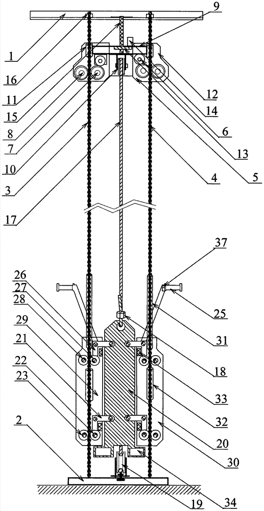
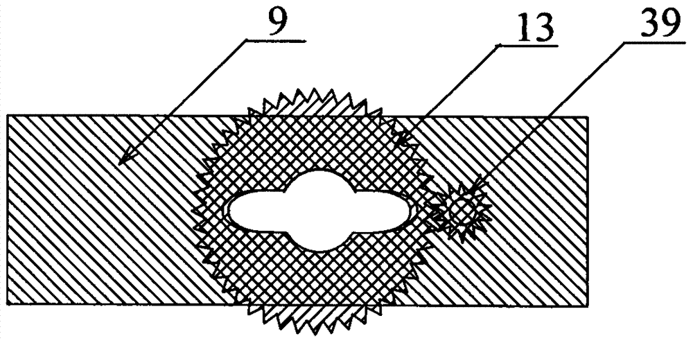
[0022] This patent includes in the accompanying drawings: the upper fixed frame (1) of the iron tower, the bottom fixed frame (2), the left steel strand (3), the right steel strand (4), the steel rope tractor (5), the upper steel rope Pulley (10), hoisting steel rope (17), bottom pulley (19), lifting frame (20), guide frame (29), lifting hoist (35) are connected together and form, wherein; upper fixed frame (1) , the bottom fixing frame (2), the left steel strand (3), the right steel strand (4) are permanently fixed on each iron tower, and the outer layers of the left steel strand (3) and the right steel strand (4) are made of stainless steel Silk production, the left steel strand (3), the right steel strand (4) are parallel and vertically passed through the insulating backing plate (45), the fixing backing plate (46), at each steel strand end by the steel strand clamp ( 16) Fix after clamping, the left steel strand (3) and the right steel strand (4) are insulated from each ot...


PUM


Abstract

The invention discloses an electric lifting device for high-voltage transmission line tower working. With regard to the current situation that the present climbing-up and climbing-down working for high-voltage transmission line towers are high in labor intensity, and the frequent accidents of falling injury are caused, the towers are provided with climbing pedals, and some irrelevant personnel privately climb the towers, so that many defects of electric shock injury, power outage and the like are caused, a steel strand fixing frame is installed at the middle of the top of each high-voltage transmission line tower, and a fixing frame is installed at the bottom of the high-voltage transmission line tower; a left steel strand and a right steel strand are fixed to the fixing frames verticallyand in parallel; a steel rope and an upper-end pulley of a lifting winch are driven to the top of the high-voltage line tower through a steel rope tractor, and are automatically locked with the fixingframe at the top; working personnel are carried to climb up and climb down the tower by a storage-battery direct-current winch on the ground; and the climbing-up and climbing-down working is rapid, efficient, safe and reliable, the labor intensity of the working personnel is greatly lowered, climbing-up and climbing-down for the pedals are avoided, the unsafe behavior of privately climbing the towers, of non-working personnel is prevented, and the safe running of a transmission line is effectively improved.

Description

technical field [0001] This patent relates to the technical field of high-voltage line operation, in particular to an electric lifting device for high-voltage line iron tower operation. Background technique [0002] At present, high-voltage transmission line towers; with the increase of voltage level, the line towers are getting higher and higher, the traditional towers work up and down, and the ladder climbing pedals installed are used to climb step by step. When the operators work on and off the tower, the consumption A lot of physical strength and labor intensity are very high, and accidents of falling injuries occur from time to time. Because the iron tower has climbing pedals, some unrelated personnel climb the iron tower privately, resulting in frequent power outages and injury accidents. Contents of the invention [0003] The purpose of this patent is to solve the current high-voltage transmission line iron tower climbing operation, which is labor-intensive, and acc...

Claims


Application Information

Patent Timeline
IPC IPC(8): B66F11/04H02G1/02
CPCY02B50/00
Inventor 徐健徐光荣何树香
Owner 宋磐
Learn More