Front suspension structure of automotive vehicle
一种前悬架、汽车的技术,应用在悬架、弹性悬架、装在枢轴上的悬臂等方向,能够解决零件个数和可动部增加等问题
- Summary
- Abstract
- Description
- Claims
- Application Information
AI Technical Summary
Problems solved by technology
Method used
Image
Examples
Embodiment Construction
[0033] One embodiment of the present invention will be described in detail below based on the drawings.
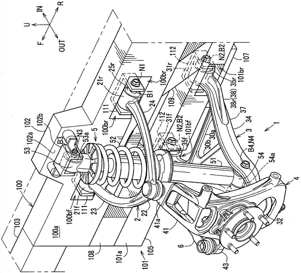
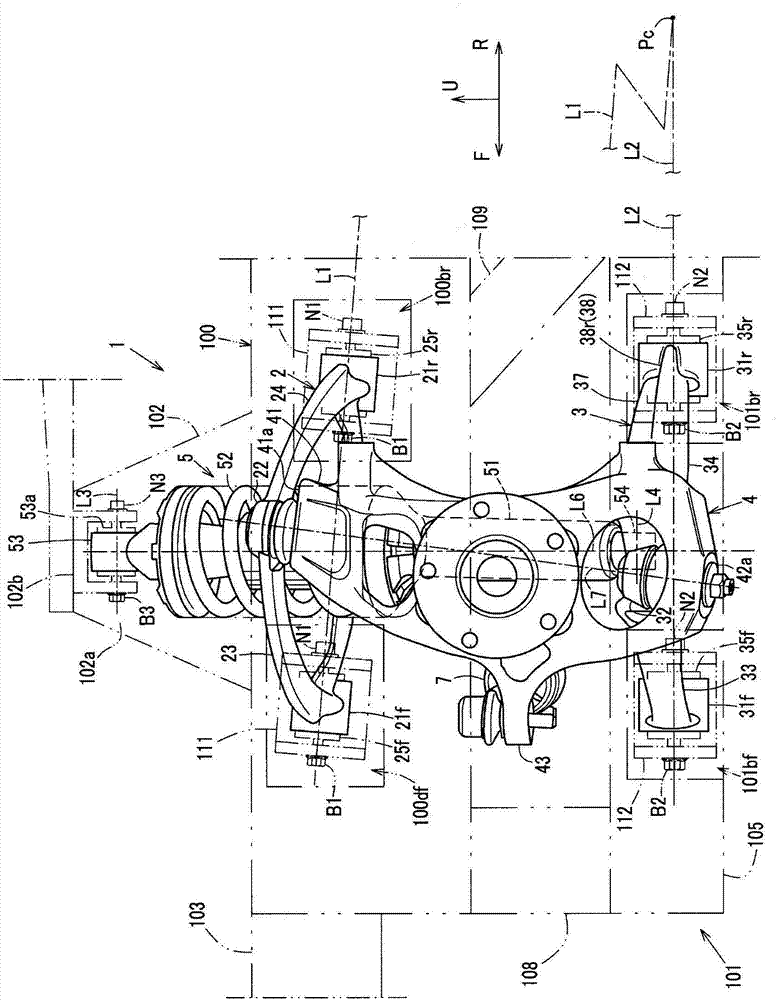
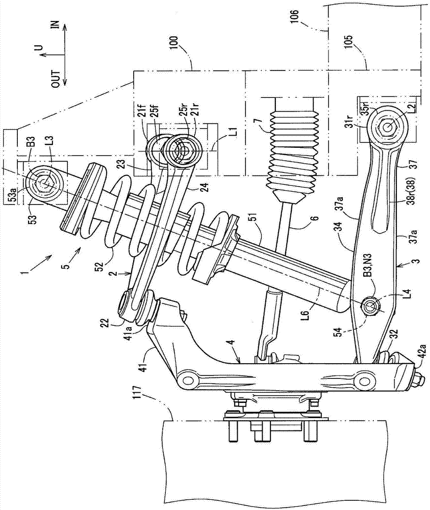
[0034] In the following description, the arrow F in the figure represents the front of the vehicle, the arrow R represents the rear of the vehicle, the arrow IN represents the inside in the vehicle width direction, the arrow OUT represents the outside in the vehicle width direction, and the arrow U represents the upper side of the vehicle.
[0035] In addition, the left and right front suspension devices 1 are bilaterally symmetrical and have the same structure, so the left front suspension device 1 will be described.
[0036] Such as figure 1 As shown, the front suspension device 1 of this embodiment is mounted on the front side frame 100 and the front sub-frame 101 provided in the front of the vehicle body, and is provided with an upper arm 2 mounted on the front side frame 100 and mounted on the front sub-frame 101 The lower arm 3, the wheel support member 4 (also referred to...
PUM
 Abstract
Description
Claims
Application Information
 - R&D Engineer
- R&D Manager
- IP Professional
- Industry Leading Data Capabilities
- Powerful AI technology
- Patent DNA Extraction
Browse by: Latest US Patents, China's latest patents, Technical Efficacy Thesaurus, Application Domain, Technology Topic, Popular Technical Reports.
© 2024 PatSnap. All rights reserved.Legal|Privacy policy|Modern Slavery Act Transparency Statement|Sitemap|About US| Contact US: help@patsnap.com


