Automatic assembling equipment for spinneret assembly
An automatic assembly and spinneret technology, applied in the direction of assembly machines, metal processing equipment, metal processing, etc., can solve the problems of high production cost and low work efficiency, improve the assembly qualification rate, improve work efficiency, and realize continuous cutting cut effect
- Summary
- Abstract
- Description
- Claims
- Application Information
AI Technical Summary
Problems solved by technology
Method used
Image
Examples
Embodiment 1
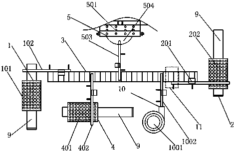
[0035] This embodiment proposes a kind of automatic assembly equipment for spinneret assembly, such as figure 1 As shown in the structure, according to the assembly sequence of the existing spinneret assembly (spinneret nut → spinneret → filter cloth → sealing ring), the automatic assembly equipment decomposes the loading or installation operations of each component to the conveyor line in sequence 3, at the same time through the corresponding grasping mechanism, the assembly workpiece of the spinneret is sent to the corresponding operation station, and the spinneret is automatically assembled on the conveying line 3, and the conveying line 3 is continuously transported. With the cooperation of the mechanism, the continuous assembly of multiple spinnerets can be realized and the assembly efficiency can be improved.
[0036] In order to cooperate with the automatic assembly process of the spinnerets on the conveying line 3, the two ends of the conveying line 3 are successively ...
Embodiment 2
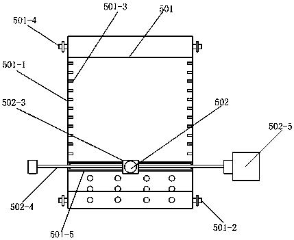
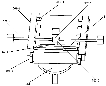
[0050] This embodiment limits the structure of the filter cloth conveying system 501 and the filter cloth cutting system 502 on the basis of the embodiment, and its structure is as follows figure 2 , image 3 as shown,
[0051] The filter cloth conveying system 501 includes a filter cloth conveying line 501-1 and rotating rollers 501-2 and synchronous rollers 501-4 respectively arranged at both ends of the filter cloth conveying line 501-1, such as figure 2 As shown, the filter cloth passes through the filter cloth conveying line 501-1 and is respectively wound on the rotating roller 501-2 and the synchronous roller 501-4. The rotating roller 501-2 is used to wind the cut filter cloth, and the synchronous roller 501 -4 is used to wind the filter cloth before cutting. When the filter cloth cutting system 502 cuts the filter cloth, the rotating roller 501-2 rotates to wind the cut filter cloth, and the synchronous roller 501-4 follows After the rotation, the filter cloth cut...
Embodiment 3
[0058] This embodiment limits the gripping mechanism of the workpiece on the basis of Embodiment 2. The filter cloth gripping mechanism 503, the spinneret nut gripping mechanism 102, the spinneret gripping mechanism 402, the sealing The working principle of the circle grabbing mechanism 1002 and the automatic grabbing mechanism 201 are the same, and the structure is the same, as Figure 4 As shown, all include a linear movement mechanism 7, a lifting mechanism 8 and a workpiece gripper 6.
[0059] In this embodiment, the workpiece gripper 6 is set on the lifting mechanism 8, and the lifting mechanism 8 is set on the linear moving mechanism 7, and the linear moving mechanism 7 can realize the movement in the X-axis and Y-axis directions in the horizontal plane. like Figure 4 As shown in the structure, the linear moving mechanism 7 is composed of a moving part and a power drive part. The moving part includes a first moving part 701 and a second moving part 702. The first movin...
PUM
 Abstract
Description
Claims
Application Information
 - Generate Ideas
- Intellectual Property
- Life Sciences
- Materials
- Tech Scout
- Unparalleled Data Quality
- Higher Quality Content
- 60% Fewer Hallucinations
Browse by: Latest US Patents, China's latest patents, Technical Efficacy Thesaurus, Application Domain, Technology Topic, Popular Technical Reports.
© 2025 PatSnap. All rights reserved.Legal|Privacy policy|Modern Slavery Act Transparency Statement|Sitemap|About US| Contact US: help@patsnap.com


