Multimode optical fiber for power-over-fiber applications

A multi-mode optical fiber and optical fiber technology, applied in clad optical fiber, graded index core/clad optical fiber, optics, etc., can solve multi-mode optical fiber attenuation and power limitation, poor efficiency of GaAs or Si photoelectric converters, etc. question

Active Publication Date: 2018-01-02
PRYSMIAN SPA
View PDF11 Cites 4 Cited by
  • Summary
  • Abstract
  • Description
  • Claims
  • Application Information

AI Technical Summary

Problems solved by technology

Due to the availability of high power laser diodes (HPLDs) operating in the 808nm window, the main limitations for PoF are the poor efficiency of GaAs or Si photoelectric converters (PV) and the attenuation and power limitations of standard multimode fiber

Method used


Image

  • Multimode optical fiber for power-over-fiber applications
  • Multimode optical fiber for power-over-fiber applications
  • Multimode optical fiber for power-over-fiber applications

Examples


Embodiment Construction

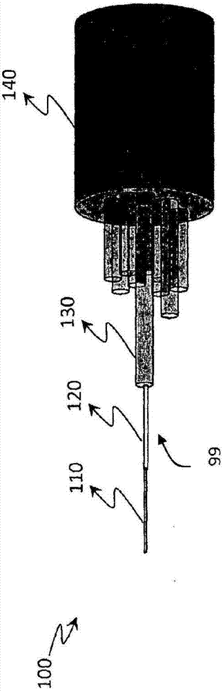
[0170] Such as figure 1 As shown, there is shown a fiber optic cable 100 comprising multimode optical fiber 99 for transmitting "high" power and preferably also data.

[0171] The multimode optical fiber 99 of the present invention may not be part of an optical cable, but may also be used as a single optical fiber.

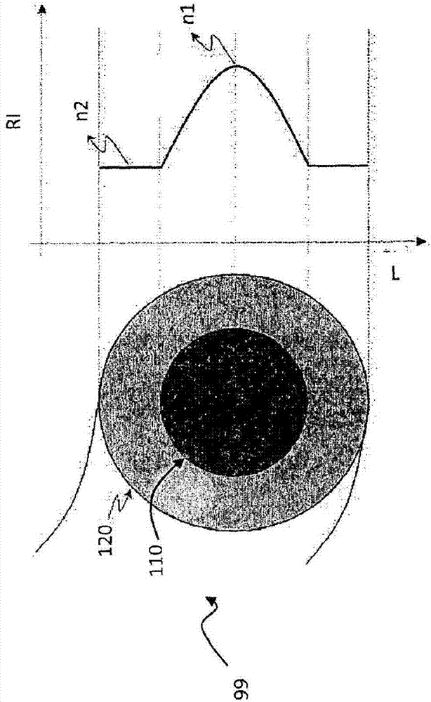
[0172] Optical fiber 99 includes a core 110 and a cladding 120 surrounded by one or more coating layers 130 for protection. Fiber optic cable 100 may include a plurality of optical fibers 99 surrounded by an outer jacket 140 for protecting the fibers from the external environment.

[0173] Figure 11 An example of one application of optical fiber 99 in a power over fiber application is shown. System 200 includes three parts: optical power source OPS (including high-power laser diode HPLD, laser diode controller LDC and optical receiver RX), remote unit RU (including sensor S, photoelectric converter PV, Fabry-Perot ( Fabry Perot) a semiconductor laser FPLD and...


PUM


Abstract

The present invention is relative to a multimode optical fiber (99) for continuous transmission of electromagnetic radiation at high power, said fiber defining a fiber axis and comprising a core (110)and a cladding (120) surrounding the core, and wherein the multimode optical fiber is a multimode graded-index fiber, the refraction index profile in the fiber essentially following the formula (1) where formula (A), Nr is the distance from the fiber axis, N(r) is the nominal refractive index as a function of distance from the fiber axis, N1 is the nominal refractive index on the axis of the fiber, N2 is the refractive index of the cladding, N a is the core radius, and Ng is a parameter that defines the shape of the profile, where the core diameter 2a is comprised between 90 Mum and 190 Mum,the parameter g is comprised between 1.2 and 1.8, and the numerical aperture (NA) of the fiber, where formula (B), is comprised between 0.2 and 0.3.

Description

technical field [0001] The present invention relates to multimode optical fibers for transmitting high power over long distances. The invention also relates to a method for transmitting high optical power over long distances. Background technique [0002] In standard form, an optical fiber consists of an optical fiber core that functions to transmit an optical signal, and an optical outer cladding that functions to confine the optical signal within the core. For this purpose, the refractive index of the core (n core ) and the refractive index of the cladding (n cladding ) should make n core >n cladding . [0003] The index profile represents a graphical representation of a function relating the index of refraction of an optical fiber to the radius. In standard fashion, the distance to the center of the fiber is shown on the x-axis, while on the y-axis the difference between the refractive index at that radial position and the refractive index of the optical outer cl...

Claims


Application Information

Patent Timeline
Patent Type & Authority Applications(China)
IPC IPC(8): G02B6/028
CPCG02B6/4296G02B6/0288
Inventor J·C·维拉达瑟尔瓦E·L·A·斯宾诺拉德索扎V·加西亚J·B·若索勒姆C·弗洛瑞迪亚M·A·B·萨恩奇斯
Owner PRYSMIAN SPA
Why Eureka
Try Eureka