Vacuum circuit breaker force reducing device
A technology for vacuum circuit breakers and vacuum tubes, which is applied to high-voltage air circuit breakers, circuits, electrical components, etc., and can solve problems such as reduced service life of equipment, difficulty in replacing switchgear components, and large force of reset springs.
- Summary
- Abstract
- Description
- Claims
- Application Information
AI Technical Summary
Problems solved by technology
Method used
Image
Examples
Embodiment 1
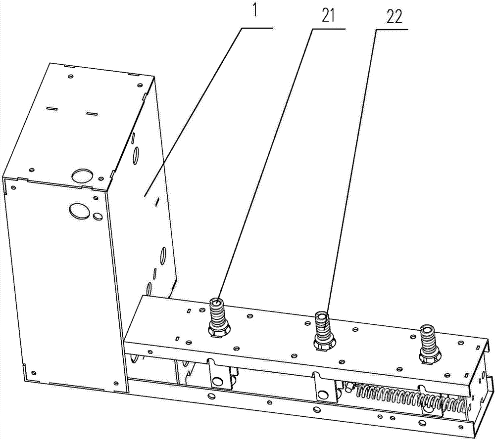
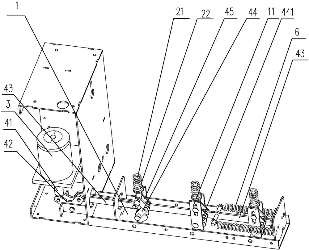
[0018] Embodiment one: by figure 1 , figure 2It can be seen that the present invention discloses an embodiment of a force reducing device for a vacuum circuit breaker, which includes a bracket 1, several vacuum tubes and a driving mechanism for driving the vacuum tubes to open and close. The vacuum tubes are arranged on the bracket 1 at intervals, The vacuum tubes are respectively provided with connecting rods 21 for opening and closing the vacuum tubes. The connecting rods 21 are sleeved with a reset spring 22 for resetting the connecting rods 21 to the opening position of the vacuum tubes. The driving mechanism includes a drive Part 3, crank arm 42 and transmission rod 41, the drive member 3 is connected to the transmission rod 41, the crank arm 42 is hingedly arranged on the bracket 1 and connected to the transmission rod 41, and the crank arm 42 is also connected to There is a main shaft 43 for driving the opening and closing of the vacuum tube, and the main shaft 43 is ...
Embodiment 2
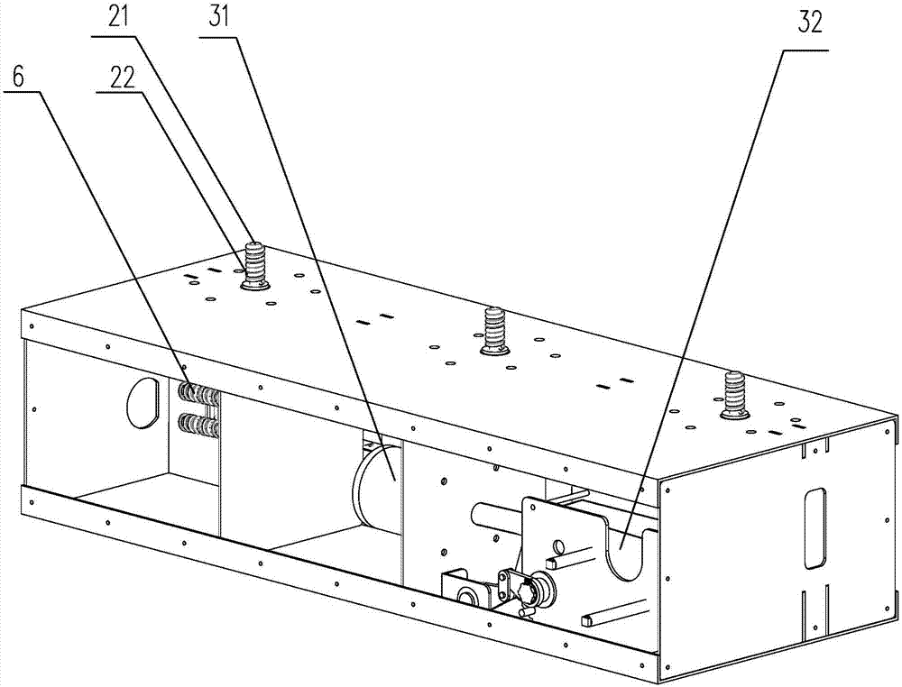
[0019] Embodiment two: by image 3 , Figure 4 It can be seen that the present invention discloses another embodiment of a force reducing device for a vacuum circuit breaker, which includes a bracket 1, several vacuum tubes and a driving mechanism for driving the vacuum tubes to open and close. The vacuum tubes are arranged on the bracket 1 at intervals The vacuum tubes are respectively provided with connecting rods 21 for opening and closing the vacuum tubes, and the connecting rods 21 are sleeved with a reset spring 22 for resetting the connecting rods 21 to the opening position of the vacuum tubes. The driving mechanism includes The drive member 3, the crank arm 42, the transmission rod 41 and the transmission group for driving the crank arm 42 to rotate, the drive member 3 includes a permanent magnet operation box 31 and a mechanical operation box 32, and the drive rod includes a first drive rod 52 and the second drive rod 53, the permanent magnet operation box 31 is conn...
PUM
 Abstract
Description
Claims
Application Information
 - Generate Ideas
- Intellectual Property
- Life Sciences
- Materials
- Tech Scout
- Unparalleled Data Quality
- Higher Quality Content
- 60% Fewer Hallucinations
Browse by: Latest US Patents, China's latest patents, Technical Efficacy Thesaurus, Application Domain, Technology Topic, Popular Technical Reports.
© 2025 PatSnap. All rights reserved.Legal|Privacy policy|Modern Slavery Act Transparency Statement|Sitemap|About US| Contact US: help@patsnap.com


