Storage automatic cable unwinding frame
A pay-off frame and automatic technology, which is applied in the direction of conveying filamentous materials, thin material handling, transportation and packaging, etc., can solve the problems of high labor intensity, low cable pay-off efficiency, high construction cost, etc., and achieve saving pay-out costs , Great promotion and application value, strong practical effect
- Summary
- Abstract
- Description
- Claims
- Application Information
AI Technical Summary
Problems solved by technology
Method used
Image
Examples
Embodiment 2
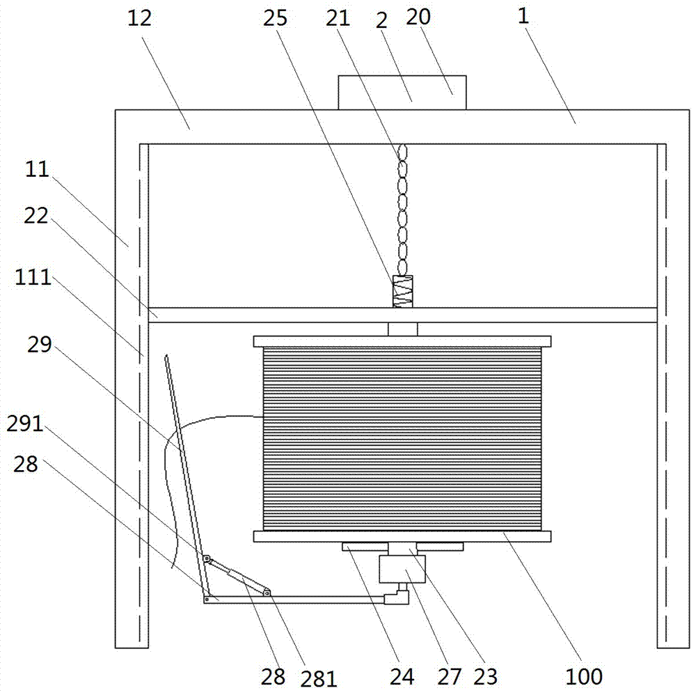
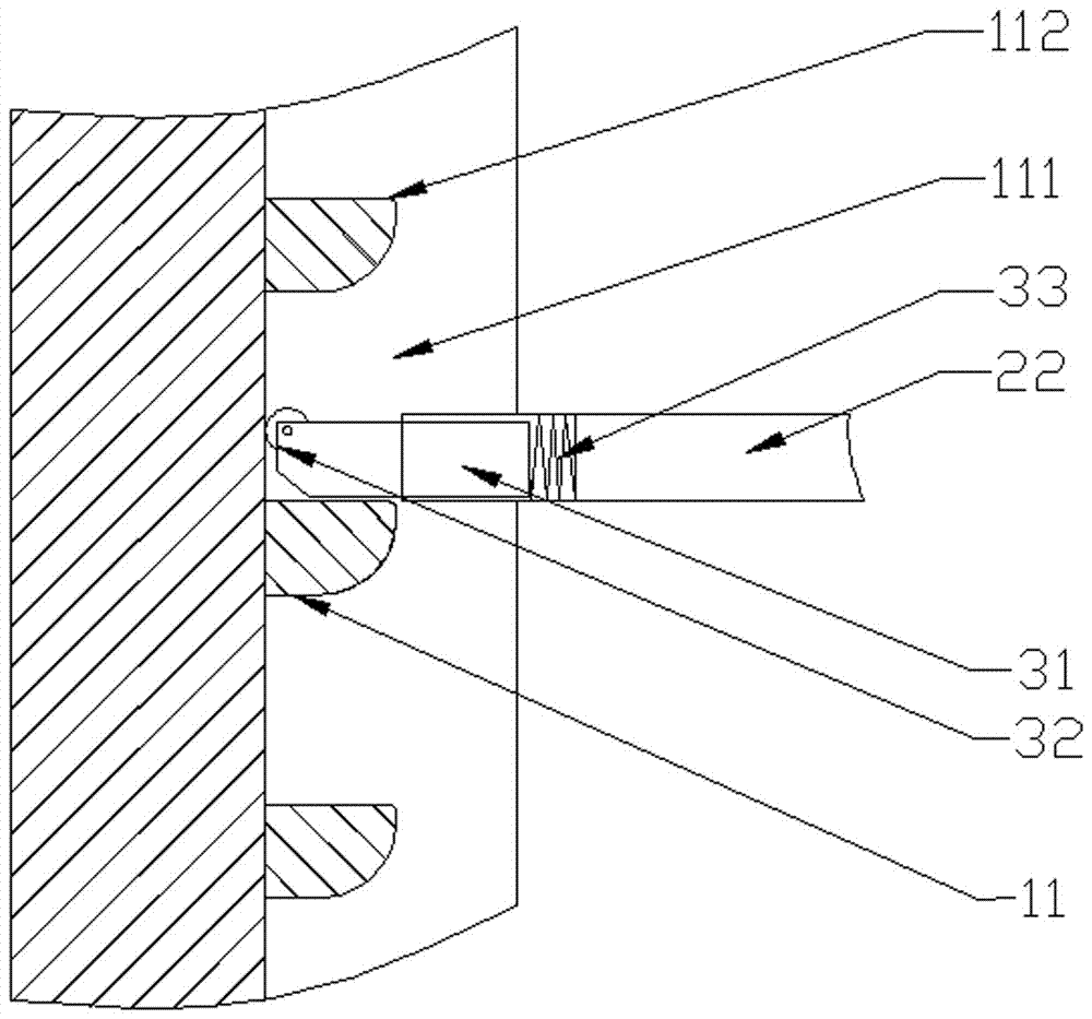
[0024] Embodiment 2, the lifting device 2 is a jacking hydraulic cylinder 112 arranged in the vertical beam 11, the telescopic cylinder of the jacking hydraulic cylinder 112 is fixedly connected with the end of the horizontal strut 22, and the vertical beam 11 is provided with a hydraulic The telescopic chute of the oil cylinder 112; setting the jacking oil cylinder instead of the hoist can also realize the lifting of the cable drum, and the lifting process is more stable and reliable. The horizontal strut 22 is provided with a connecting spring 26 , and the horizontal strut 22 is fixedly connected to the connecting shaft 23 through the connecting spring 26 . A connecting spring is set between the connecting shaft and the horizontal support rod to ensure that the cable is lowered from the cable reel more reliably. When the jacking hydraulic cylinder starts and stops, the connecting spring vibrates up and down, which in turn drives the cable reel to vibrate up and down, thereby ...
Embodiment 3
[0025] Embodiment 3, the lifting device 2 is a jacking hydraulic cylinder 112 and a lifting hydraulic cylinder 115 arranged in the vertical beam 11, the jacking hydraulic cylinder 112 is arranged at the bottom end of the vertical beam 11, and the lifting hydraulic cylinder 115 is arranged at the bottom of the vertical beam 11. 11, the telescopic cylinders of jacking hydraulic cylinder 112 and lifting hydraulic cylinder 115 are fixedly connected to the ends of horizontal struts 22, and vertical beams 11 are provided with chutes for jacking hydraulic cylinder 112 and lifting hydraulic cylinder 115 to expand and contract. . The jacking hydraulic cylinder and the lifting hydraulic cylinder are set as the lifting device, which can lift the cable reel more quickly and stably, and the rapid lifting is also conducive to speeding up the cable pay-off rate.
[0026]The horizontal strut 22 is provided with a connecting spring 26 , and the horizontal strut 22 is fixedly connected to the c...
Embodiment 4
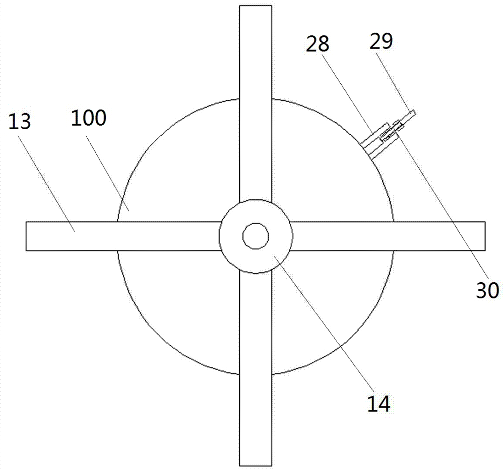
[0027] Embodiment 4, the lower end of the connecting shaft 23 is provided with a rotating motor 27, the rotating shaft of the rotating motor 27 is vertically downward, the rotating shaft is connected with a horizontally arranged rotating bar 28, and one end is connected to the rotating shaft of the rotating motor 27. It is fixedly connected, and the other end is hinged with a wire pulling rod 29 , the length of the rotating cross bar 28 is greater than the radius of the cable reel 100 , and the length of the wire pulling rod 29 is greater than the axial length of the cable reel 100 . Driven by the rotating motor, the wire pulling lever can rotate around the cable reel, and the released cable is placed outside the wire pulling frame. The speed of the cable can be further accelerated under the rotation of the wire pulling lever, and it solves the problem that the cable depends on itself. Gravity is not sufficient to ensure continuous pay-off problems.
[0028] A first connecting...
PUM
 Abstract
Description
Claims
Application Information
 - R&D Engineer
- R&D Manager
- IP Professional
- Industry Leading Data Capabilities
- Powerful AI technology
- Patent DNA Extraction
Browse by: Latest US Patents, China's latest patents, Technical Efficacy Thesaurus, Application Domain, Technology Topic, Popular Technical Reports.
© 2024 PatSnap. All rights reserved.Legal|Privacy policy|Modern Slavery Act Transparency Statement|Sitemap|About US| Contact US: help@patsnap.com


