
Kitchen waste crushing device capable of realizing solid-liquid separation function

A technology of kitchen waste and crushing device, which is applied in the direction of filtration and separation, separation method, fixed filter element filter, etc., can solve the problems of easy generation of biogas, easy corruption, safety problems, etc., achieve efficient crushing treatment, and reduce noise pollution , the effect of reasonable structural design

Inactive Publication Date: 2017-12-22
单开禹
View PDF7 Cites 13 Cited by
  • Summary
  • Abstract
  • Description
  • Claims
  • Application Information

AI Technical Summary

Problems solved by technology

[0002] At present, landfill is the most common way to recycle kitchen waste, but with the increasing amount of waste, the disadvantages of landfill gradually appear, and because it contains a lot of organic matter, it is very easy to rot and deteriorate, and it is easy to produce waste after landfill. Biogas is prone to safety problems; there are currently some harmless treatment methods for kitchen waste, mainly by crushing it first, then drying and pressing it to form dry and relatively small waste; there are also biogas treatments through microorganisms. Manufacture and many other methods; however, there is no special treatment for its crushing device, and since crushing is often the first step in treatment, and kitchen waste has a lot of water; therefore, we need a kitchen waste that can separate solids and liquids crushing device

Method used


Image

  • Kitchen waste crushing device capable of realizing solid-liquid separation function
  • Kitchen waste crushing device capable of realizing solid-liquid separation function
  • Kitchen waste crushing device capable of realizing solid-liquid separation function

Examples


Embodiment Construction

[0015] The technical solution of this patent will be further described in detail below in conjunction with specific embodiments.

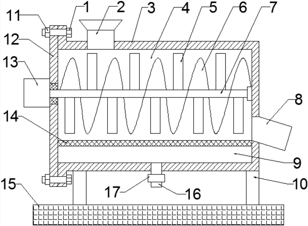
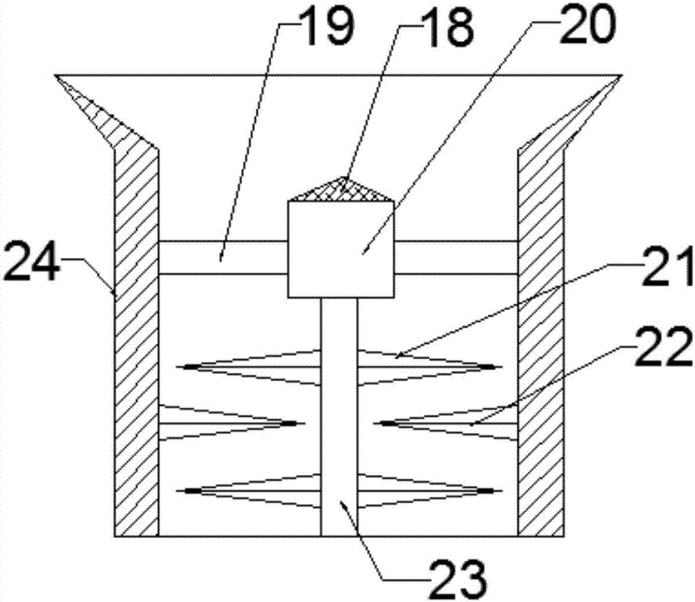
[0016] see figure 1 , this embodiment provides a kitchen waste crushing device capable of solid-liquid separation, including a housing 3, a crushing rod 5, a discharge port 8, a cover plate 12, a base 15 and a drain pipe 16; the housing 3 Horizontally arranged above the base 15, the inside of the housing 3 is provided with a crushing chamber 4 and a sewage chamber 9; the base 15 is arranged directly below the housing 3, and the housing 3 is fixedly connected to the base 15 through the support column 10; the housing 3 The top is provided with a feeding device 2, and the left end is provided with a cover plate 12; the cover plate 12 is fixedly connected to the left end of the housing 3 by screwing bolts 1 and nuts 11, and a transmission device is provided on the left center line of the cover plate 12 13. The crushing chamber 4 is provided with a cru...


PUM


Abstract

The invention discloses a kitchen waste crushing device capable of realizing a solid-liquid separation function, and belongs to the field of recycling treatment of household garbage. The device comprises a shell, crushing rods, a discharge port, a cover plate, a base and a liquid drainage pipe, wherein the shell is horizontally arranged above the base; a crushing cavity and a sewage cavity are formed in the shell; the base is arranged right below the shell; the shell is fixedly connected with the base through supporting columns; a feeding device is arranged at the top of the shell; the cover plate is arranged at the left end of the shell; a rotating shaft is horizontally arranged on the center line of the crushing cavity; the left end of the rotating shaft penetrates through the cover plate through a bearing and is connected with a transmission device; a feeding tank is fixedly arranged on the top of the left side of the shell; the interior of the feeding tank is provided with a crushing motor through a fixing frame; and a material guide cone is fixedly arranged at the top end of the crushing motor. According to the kitchen waste crushing device capable of realizing the solid-liquid separation function, the device is reasonable in structural design, low in noise and capable of realizing the solid-liquid separation function for kitchen waste in the crushing process, the kitchen waste is thoroughly and uniformly crushed, and later treatment is facilitated.

Description

technical field [0001] The invention relates to the field of recovery and reuse treatment of domestic garbage, in particular to a kitchen waste crushing device capable of solid-liquid separation. Background technique [0002] At present, landfill is the most common way to recycle kitchen waste, but with the increasing amount of waste, the disadvantages of landfill gradually appear, and because it contains a lot of organic matter, it is very easy to rot and deteriorate, and it is easy to produce waste after landfill. Biogas is prone to safety problems; there are currently some harmless treatment methods for kitchen waste, mainly by crushing it first, then drying and pressing it to form dry and relatively small waste; there are also biogas treatments through microorganisms. Manufacture and many other methods; however, there is no special treatment for its crushing device, and since crushing is often the first step in treatment, and kitchen waste has a lot of water; therefore, ...

Claims


Application Information

Patent Timeline
IPC IPC(8): B02C21/00B02C23/02B02C23/16B02C13/13B02C18/10B02C18/18B02C19/22B01D29/01
CPCB02C21/00B01D29/01B02C13/13B02C18/10B02C18/18B02C19/22B02C23/02B02C23/16B02C2023/165B02C2201/06
Inventor 单开禹汤沛东
Owner 单开禹
Learn More