Planing and milling wheel control mechanism of a milling machine

A technology of control mechanism and milling machine, which is applied in the field of machinery, can solve the problems of poor reliability of hydraulic system, poor transmission stability, and low mechanical efficiency, and achieve the effects of improving bearing capacity, improving force, and low manufacturing cost

Active Publication Date: 2019-08-02
嘉兴汉羿文化传播有限公司
View PDF9 Cites 0 Cited by
  • Summary
  • Abstract
  • Description
  • Claims
  • Application Information

AI Technical Summary

Problems solved by technology

The power of the milling depth adjustment device comes from its hydraulic system. Although the hydraulic system has a compact structure, the hydraulic system is easily affected by oil temperature overheating, low mechanical efficiency, poor transmission stability, and poor reliability of the hydraulic system. Maintenance and maintenance are complicated and costly.

Method used


Image

  • Planing and milling wheel control mechanism of a milling machine
  • Planing and milling wheel control mechanism of a milling machine
  • Planing and milling wheel control mechanism of a milling machine

Examples


Embodiment 1

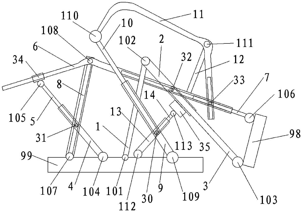
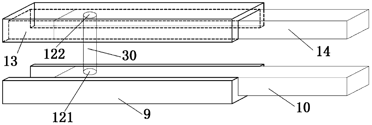
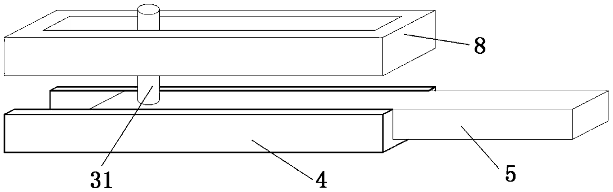
[0035] The planing and milling wheel control mechanism of the milling machine, including pole one 1, pole two 2, pole three 3, pole four 4, pole five 5, pole six 6, pole seven 7, pole eight 8, pole nine 9, pole ten 10 , rod eleven 11, rod twelve 12, rod thirteen 13, rod fourteen 14, shaft rod 30, first cylindrical pin 31, second cylindrical pin 32, third cylindrical pin 33, sliding sleeve 34, slider 35 , actuator 98 and frame 99,

[0036] One end of rod one 1 is connected to the frame 99 through rotating pair one 101, the other end of rod one 1 is connected to one end of rod two 2 through rotating pair two 102, and the other end of rod two 2 is connected to one end of rod three 3 through an axial movement pair to form The telescopic rod, the other end of the rod three 3 is connected to the actuator 98 through the rotating pair three 103,

[0037] One end of rod four 4 is connected on the frame 99 by rotating pair four 104, the other end of rod four 4 is connected with one end...


PUM


Abstract

The invention discloses a planing and milling wheel controlling mechanism for a planing and milling machine. One end of a rod 1 is connected to a rack; the other end of the rod 1 is connected with one end of a rod 2; the other end of the rod 2 is connected with one end of a rod 3 through an axial mobile pair; the other end of the rod 3 is connected to an actuator; one end of a rod 4 is connected to the rack while the other end of the rod 4 is connected with one end of a rod 5 through an axial mobile pair; the other end of the rod 5 is connected to a sliding bush; the sliding bush is mounted at one end of a rod 6 in a sleeving manner; the other end of the rod 6 is connected with one end of a rod 7 through an axial mobile pair; the other end of the rod 7 is connected to the actuator; one end of a rod 9 is connected to the rack while the other end of the rod 9 is connected with one end of a rod 10 through an axial mobile pair; the other end of the rod 10 is connected with one end of a rod 11; one end of a rod 13 is connected to the rack while the other end of the rod 13 is connected with one end of a rod 14 through an axial mobile pair; the other end of the rod 14 is connected to a sliding block; one end of a shaft rod is connected to the rod 10 through an axial mobile pair 21 while the other end of the shaft rod is connected to the rod 14 through an axial mobile pair 22.

Description

technical field [0001] The invention relates to the field of machinery, in particular to a planing and milling wheel control mechanism of a milling machine. Background technique [0002] Road milling machine is one of the main types of asphalt pavement maintenance construction machinery, and also one of the main equipment for asphalt concrete pavement maintenance construction. Defects such as oil waves, textures, and ruts can also be used to excavate pits and grooves on the road surface, as well as roughening of the cement road surface and milling of the surface layer. Because of its high working efficiency, simple construction process, easy control of milling depth, convenient and flexible operation, good maneuverability, and the old milling materials can be directly recycled, etc., it is widely used in urban municipal roads and highway maintenance projects. [0003] A general milling machine is composed of an engine, a frame, a milling rotor (planing and milling wheel), a...

Claims


Application Information

Patent Timeline
Patent Type & Authority Patents(China)
IPC IPC(8): E01C23/088
CPCE01C23/088
Inventor 不公告发明人
Owner 嘉兴汉羿文化传播有限公司
Why Eureka
Try Eureka