
Multifunctional nursing bed

A nursing bed, multi-functional technology, applied in the field of medical machinery, can solve the problems of physical exertion, increased patient treatment costs, inconvenient operation, etc., and achieve the effect of reducing workload, reducing risks and pain, and reducing workload

Inactive Publication Date: 2017-12-19
崔林
View PDF3 Cites 0 Cited by
  • Summary
  • Abstract
  • Description
  • Claims
  • Application Information

AI Technical Summary

Problems solved by technology

[0004] However, for patients who often need to go outside to breathe fresh air, they often need to move the patient from the hospital bed to the wheelchair. On the one hand, this work makes the nursing workers or the patient's family members consume physical strength when moving the patient; , some special patients need to be very careful when moving due to the special location of the wound, which makes the work difficult for the nursing staff, and at the same time causes unnecessary accidental dangers when the patient moves, such as the dehiscence of the wound, etc.
In addition, the method of moving the patient from the lake bed to the wheelchair makes the patient need to be equipped with a wheelchair when hospitalized, which on the one hand causes the occupancy of hospital space, and on the other hand increases the treatment cost of the patient
[0005] In addition, the current nursing bed often requires the patient to move his or her belongings when the patient changes the ward, which makes the operation inconvenient. In addition, due to the inconvenient movement of some patients, it causes great inconvenience when changing the ward. difficulty

Method used


Image

  • Multifunctional nursing bed
  • Multifunctional nursing bed
  • Multifunctional nursing bed

Examples


Embodiment 1

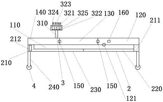
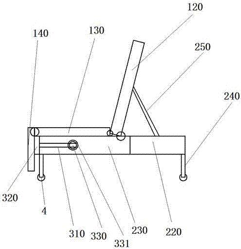
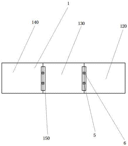
[0029] Please refer to Figure 1-Figure 4 ,in figure 1 A structural schematic diagram of a multifunctional nursing bed is provided for the present invention; figure 2 Provide the present invention with a schematic diagram of the structure when the nursing bed is changed into a wheelchair; image 3 Provide a schematic structural diagram of the upper layer for the present invention; Figure 4 Provide the structural representation of the lower layer for the present invention; Figure 5 A structural schematic diagram of a folding plate is provided for the present invention.

[0030] Specifically, the present embodiment provides a multifunctional nursing bed, comprising an upper layer 1, a lower layer 2, a folding plate 3, and universal wheels 4; wherein, a sliding bar 110 is provided on the lower side of the edge of the upper layer 1; , the middle part 130, and the rear end part 140; the front end part 120 and the middle part 130 are connected through the middle rotating shaf...


PUM


Abstract

The invention discloses a multifunctional nursing bed. The multifunctional nursing bed comprises an upper layer, a lower layer, a foldable plate and universal wheels. A sliding strip is arranged on the lower side face of the edge of the upper layer; the upper layer is composed of a front end part, a middle part and a back end part; the length of the front end part is 0.8 M, the length of the middle part is 0.5 M, and the length of the back end part is 0.5 M; the front end part is connected with the middle part through a middle rotating shaft; the middle part is connected with the back end part through a middle rotating shaft; a sliding way is arranged on the upper side face of the edge of the lower layer and used for installing the sliding strip of the upper layer, and the lower layer is composed of a front supporting part and a back supporting part; one end of the sliding way is a fixing blockading limiting end, and the other end of the sliding way is provided with a stretching limiting rod; the length of the front supporting part is 1 M, two supporting legs are arranged at the front end of the front supporting part, and pulleys are arranged on the inner sides of the two side faces of the front supporting part; the length of the back supporting part is 0.8 M, two supporting legs are arranged at the back end of the back supporting part, and sliding rails are arranged on the outer sides of the two side faces of the back supporting part; the foldable plate is installed on the lower layer.

Description

technical field [0001] The invention relates to the field of medical machinery, in particular to a multifunctional nursing bed. Background technique [0002] ​The multifunctional nursing bed is developed by ourselves based on the pain suffered by patients who have been bedridden for many years and the opinions put forward by professors in major hospitals. It is specially designed for the special needs of patients who cannot take care of themselves, the disabled, paralyzed patients and pregnant women. It adopts a unique double-fold structure, and the bed surface is a special cushion structure, so that the bed surface can be adjusted to be flat or lying at will. Nursing bed with functions such as standing up and defecating (closed and flushable to reduce indoor odor) devices, the side of the nursing bed adopts a unique design as a physiotherapy magnetic pad, which plays a role in health care, stimulates blood circulation, improves nursing level, improves Improve the quality o...

Claims


Application Information

Patent Timeline
IPC IPC(8): A61G7/015A61G7/05A61G5/00A61J7/04
CPCA61G7/015A61G5/006A61G7/05A61G2203/70A61J7/0418A61J2200/70
Inventor 崔林
Owner 崔林
Learn More