Breath-type waterproof power source structure

A technology of power supply and circuit board, which is applied in the direction of electrical components, electrical equipment shell/cabinet/drawer, casing/cabinet/drawer parts, etc., which can solve the problems of increasing gaps, gaps, etc., and achieve pressure balance Effect

Pending Publication Date: 2017-12-15
惠州市华阳光电技术有限公司
View PDF21 Cites 0 Cited by
  • Summary
  • Abstract
  • Description
  • Claims
  • Application Information

AI Technical Summary

Problems solved by technology

[0002] With the rapid development of the power supply industry, more and more electronic and electrical equipment adopts an external power supply structure. Due to the particularity of its application environment, this external power supply structure requires a better waterproof effect. Therefore, the waterproof structure of the power supply becomes difficult. It is a big problem in the power supply industry. At present, many manufacturers use heat-conducting sealant to fill the power supply case. This method has a fatal drawback: when the power supply is working, the high temperature inside the power supply causes the potting compound to expand, which is harmful to the power supply case. When the power supply is not working, the internal cooling shrinks, generating negative pressure and increasing the gap

Method used


Image

  • Breath-type waterproof power source structure
  • Breath-type waterproof power source structure
  • Breath-type waterproof power source structure

Examples


Embodiment Construction

[0020] The breathable waterproof power supply structure of the present invention will be further described in detail below in conjunction with specific embodiments and accompanying drawings.

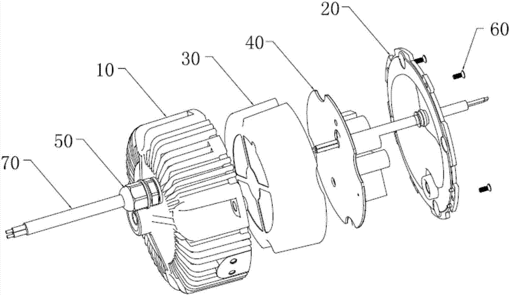
[0021] See figure 1 , a breathable waterproof power supply structure, which includes a cylindrical cup-shaped face cover 10, a circuit board 40 and an insulating sheet 30 are arranged in the face cover 10, the insulating sheet 30 is sleeved on the outside of the circuit board 40, and the circuit board 40 is connected with a wire 70 , and one end of the wire 70 passes through the insulating sheet 30 and the cover 10 to protrude to the outside. For ease of understanding and setting forth this scheme, take the cup-shaped opening of the face cover 10 as a reference plane in this case, and the direction extending toward the outside is behind, and the other direction opposite to it (that is, the cup-shaped bottom located at the face cover) One side) is the front.

[0022] preferred, see also...


PUM


Abstract

The present invention relates to a breath-type waterproof power source structure. The breath-type waterproof power source structure comprises a surface cover; a circuit board and an insulating sheet are arranged in the surface cover; the opening of the surface cove is provided with a power source bottom cover assembly in a sealed manner; the power source bottom cover assembly includes a sealing plate and a bottom cover which are in airtight connection with each other; and a protruding airbag cavity is formed on the sealing plate. When a pouring sealant is heated and expands, the airbag cavity contracts due to pressure and discharges air to the outside of the power source; when the pouring sealant contracts, the airbag cavity expands and inhales air from the outside; and therefore, pressure inside and outside the power source can be balanced. According to the breath-type waterproof power source structure of the invention, by means of the principle of expansion with heat and contraction with cold, the airbag cavity can perform a breath-like action; in the breath process of the airbag cavity, positive pressure and negative pressure generated by the expansion of the interior of the power source with heat and the contraction of the interior of the power source with cold can be effectively eliminated, and therefore, the pressure inside and outside the power source can be balanced, water cannot enter and go out from the power source, a waterproof effect is realized, and the serious problem of damage to the power source structure due to the expansion of the pouring sealant with heat and the contraction of the pouring sealant with cold can be solved.

Description

technical field [0001] The invention relates to the technical field of power supply structures, in particular to a breathable waterproof power supply structure. Background technique [0002] With the rapid development of the power supply industry, more and more electronic and electrical equipment adopts an external power supply structure. Due to the particularity of its application environment, this external power supply structure requires a better waterproof effect. Therefore, the waterproof structure of the power supply becomes difficult. It is a big problem in the power supply industry. At present, many manufacturers use heat-conducting sealant to fill the power supply case. This method has a fatal drawback: when the power supply is working, the high temperature inside the power supply causes the potting compound to expand, which is harmful to the power supply case. When the power supply is not working, the internal cooling shrinks, generating negative pressure and increa...

Claims


Application Information

Patent Timeline
Patent Type & Authority Applications(China)
IPC IPC(8): H05K5/02H05K5/06
CPCH05K5/0213H05K5/068
Inventor 杨国良陈叠峰王海鸥
Owner 惠州市华阳光电技术有限公司
Why Eureka
Try Eureka