
Radiograph drying machine

A technology of drying film and film, applied in the field of radiographic film drying machine, which can solve the problems of uneven drying of radiographic film, blurring of radiographic film, and affecting the quality of dry film, so as to avoid blurring of development, promote internal flow, and improve drying quality effect

Inactive Publication Date: 2017-12-15
武汉时代金丰仪器有限公司
View PDF7 Cites 2 Cited by
  • Summary
  • Abstract
  • Description
  • Claims
  • Application Information

AI Technical Summary

Problems solved by technology

[0002] Radiographic negative film is a very important basis for flaw detection judgment. After cleaning, radiographic negative film needs to be dried, and the process of drying film is generally carried out in drying equipment, or dried indoors. The current drying equipment for dry film mainly uses heating The lamp is heated, and the fan is used to supply air to speed up the internal and external air flow, so that the film is heated and dried. However, in this drying method, the heating source on the film dryer is fixed somewhere, and on the one hand, it causes the film dryer to dry the radiographic film. On the one hand, the radiographic film near the heating source is heated for a long time, which will easily lead to the high temperature of the radiographic film at this part, and the high temperature of the dry film will cause the development of the radiographic film to be blurred, thus affecting the quality of the dry film. During the drying process, in order to speed up the drying speed, ventilation is used to promote the air flow inside the drying machine, but the dust carried by the outside air of the drying machine can easily cause the pollution of radiographs

Method used


Image

  • Radiograph drying machine
  • Radiograph drying machine
  • Radiograph drying machine

Examples


Embodiment

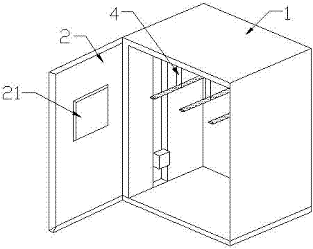
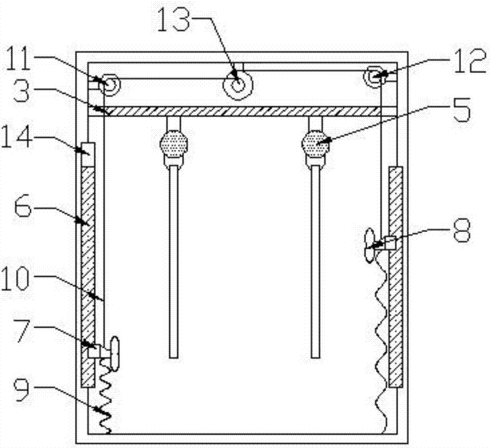
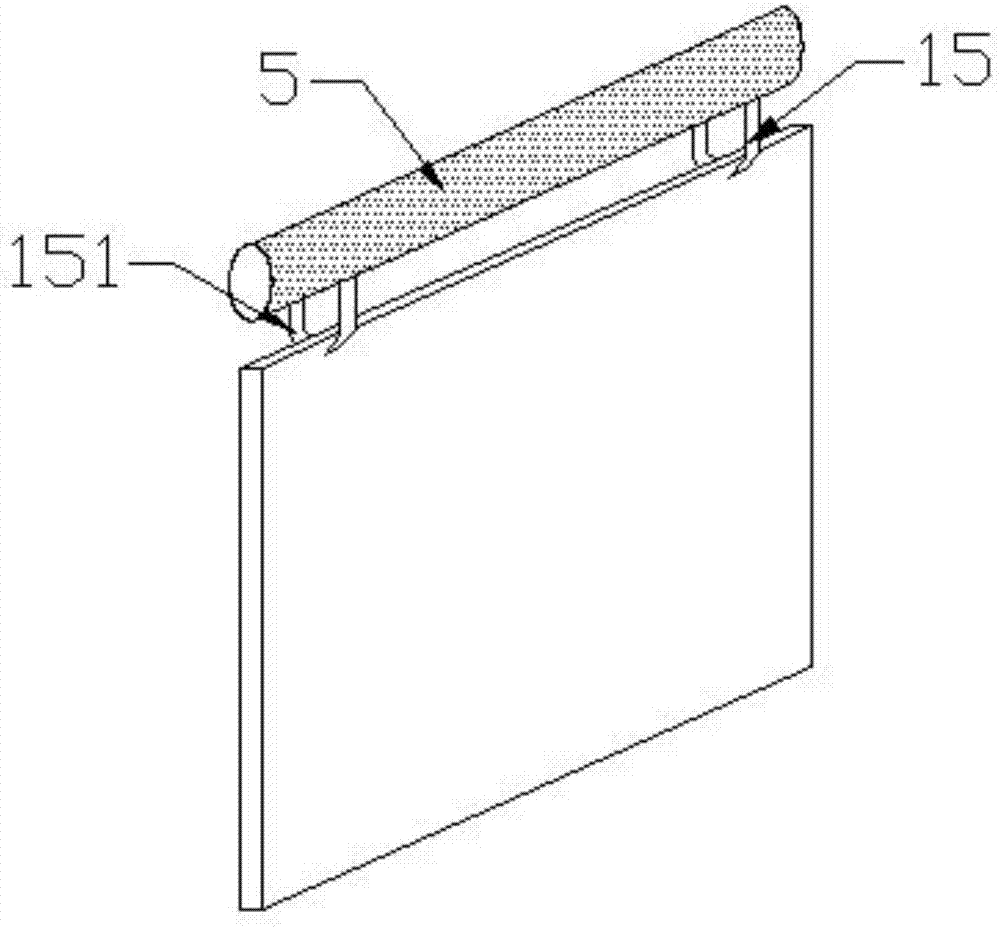
[0018] Such as Figure 1-3 As shown, a radiographic film drying machine includes a film drying machine housing 1, a machine door 2, a radiographic film suspension rod 5 and a temperature-controlling hot air blower 8, and an organic door 2 is installed on one side of the film drying machine housing 1 The top of the film drying machine housing 1 is equipped with a horizontal plate 3 through the connecting rod 4, and the bottom of the horizontal plate 3 is equipped with a plurality of radiographic negative film suspension rods 5, and the two opposite sides of the film drying machine housing 1 A side guide rail 6 is installed on the side, and a slide seat 7 is slidably installed on the side guide rail 6, and a temperature control hot air blower 8 is installed on the slide seat 7, and the bottom of the slide seat 7 is connected with the back spring 9. One end is connected, and the other end of described back-moving spring 9 is installed on the bottom of drying sheet machine housing...


PUM


Abstract

The invention discloses a radiograph drying machine. The machine includes a drying machine shell, a machine door, radiograph hanging rods and a temperature control hot-air machine, wherein one side of the drying machine shell is provided with the machine door, and the top of the drying machine shell is provided with a cross plate through a connecting rod; the bottom of the cross plate is provided with the multiple radiograph hanging rods, and the two opposite sides of the interior of the drying machine shell are provided with side guide rails. According to the radiograph drying machine, through the arrangement of the temperature control hot-air machine, temperature control drying can be conducted on radiographs inside the drying machine shell so as to avoid that radiograph developing is vague since the temperature is higher than 55 DEG C, which effectively improves the drying quality of the drying machine to the radiographs; moreover, the temperature control hot-air machine can move in the drying machine; on the one hand, the drying efficiency of the radiographs is improved, the drying cost of the radiographs is reduced, and the caused pollution to the radiographs when the radiographs are dried is prevented; on the other hand, the radiograph drying uniformity of the drying machine is improved, and it is avoided that uneven drying caused by heating source fixing influences developing.

Description

technical field [0001] The invention relates to the technical field of film drying equipment, in particular to a radiographic negative film drying machine. Background technique [0002] Radiographic negative film is a very important basis for flaw detection judgment. After cleaning, radiographic negative film needs to be dried, and the process of drying film is generally carried out in drying equipment, or dried indoors. The current drying equipment for dry film mainly uses heating The lamp is heated, and the fan is used to supply air to speed up the internal and external air flow, so that the film is heated and dried. However, in this drying method, the heating source on the film dryer is fixed somewhere, and on the one hand, it causes the film dryer to dry the radiographic film. On the one hand, the radiographic film near the heating source is heated for a long time, which will easily lead to the high temperature of the radiographic film at this part, and the high temperat...

Claims


Application Information

Patent Timeline
IPC IPC(8): G03D15/02
CPCG03D15/027
Inventor 付中强张翠云付仁长
Owner 武汉时代金丰仪器有限公司
Learn More