Packaging structure and method for electric plugging-pulling mechanism of launching device

A plug-in mechanism and launching device technology, which is applied in the direction of projectiles, weapon accessories, ammunition, etc., can solve the problems of complex space positioning and fastening of metal plates, ablation of plug-in mechanism, and difficult operation, so as to save launch preparation time , Simplified installation, solve the effect of on-site installation

Active Publication Date: 2017-12-15
SHANGHAI INST OF ELECTROMECHANICAL ENG
View PDF3 Cites 0 Cited by
  • Summary
  • Abstract
  • Description
  • Claims
  • Application Information

AI Technical Summary

Problems solved by technology

[0002] At present, the detection and power supply of the missile on the launcher are realized through the shedding plug and the socket. The socket is radially installed on the missile, and the shedding plug is installed on the electric plug-in mechanism. The bottom surface of the electric plug-in mechanism is fixed on the lower surface of the inner cavity of the launcher. , When the missile is launched, it drives the shedding plug to move forward and downward to realize separation from the socket. The wake of the missile has a strong ablation on the plugging mechanism. Since the plug-in mechanism has been plugged in place with the missile, the flame shield box needs to be spliced ​​on site by multiple metal plates, and the spatial positioning and fastening of the metal plates in the cavity of the launcher is relatively complicated, and the operation is difficult and time-consuming

Method used


Image

  • Packaging structure and method for electric plugging-pulling mechanism of launching device
  • Packaging structure and method for electric plugging-pulling mechanism of launching device
  • Packaging structure and method for electric plugging-pulling mechanism of launching device

Examples


Embodiment Construction

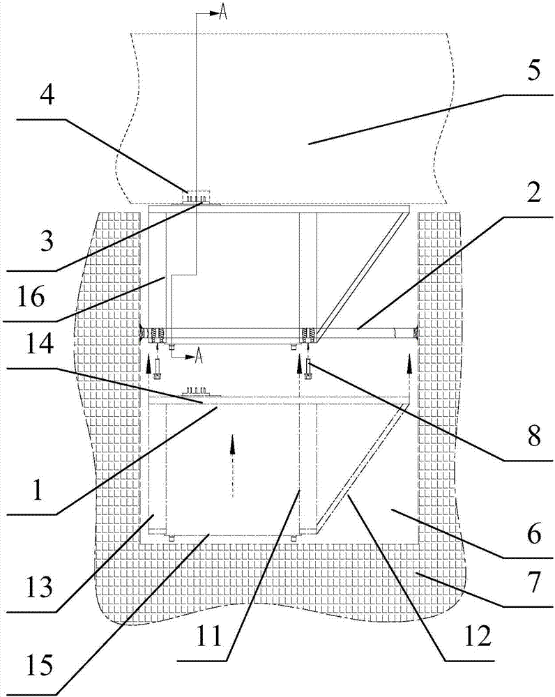
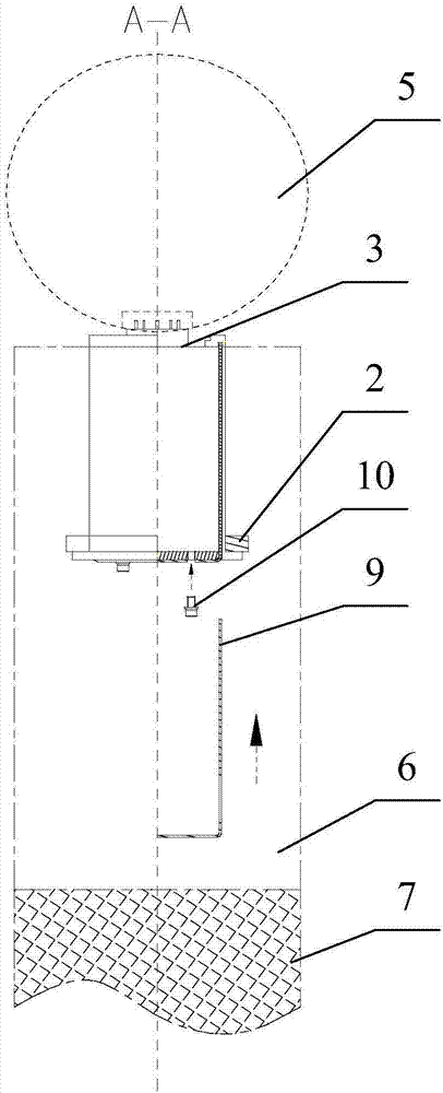
[0022] The preferred embodiments of the present invention are given below in conjunction with the accompanying drawings to describe the technical solution of the present invention in detail.

[0023] Such as Figure 1 to Figure 3 As shown, the packaging structure of the electric plug-in mechanism of the launcher of the present invention includes a plug-in mechanism box body mounting plate 2, an electric plug 3, a projectile socket 4, a projectile 5, a launcher cavity 6, a launcher body 7, a plug-in mechanism Mechanism box set screw 8, flame shield 16, a plug-in mechanism box 1 includes rear cover plate 11, diagonal brace 12, front cover plate 13, upper cover plate 14, bottom plate 15, cover plate installation includes cover plate 9 , sealing plate set screw 10, the plug-in mechanism box body 1 is positioned at the bottom of the plug-in mechanism box body mounting plate 2, the plug-in mechanism box body mounting plate 2 is connected with the plug-in mechanism box body set screw...


PUM


Abstract

The invention discloses a packaging structure and method for an electric plugging-pulling mechanism of a launching device. The packaging structure comprises a plugging-pulling mechanism box body mounting plate, an electric plug, a projectile body socket, a projectile body, a launching device cavity, a launching device body and a plugging-pulling mechanism box body set screw; a packaging plate mounting part comprises a blanking plate and a packaging plate set screw; one plugging-pulling mechanism box body is located below the plugging-pulling mechanism box body mounting plate; the plugging-pulling mechanism box body mounting plate is connected with the plugging-pulling mechanism box body set screw; the electric plug is connected with the projectile body through the projectile body socket; the projectile body socket is located on the top of the electric plug; the projectile body is located on the top of the projectile body socket; the launching device cavity is located on the right side of the plugging-pulling mechanism box body; and the plugging-pulling mechanism box body set screw is located at the bottom of the plugging-pulling mechanism box body mounting plate. According to the packaging structure, mounting of the plugging-pulling mechanism and a plugging-pulling mechanism flame-blocking plate can be simplified, so that the launch preparing time is saved, launching efficiency is improved, and the difficult problems of filed installation of the plugging-pulling mechanism and the flame-blocking plate of the launching device are effectively solved.

Description

technical field [0001] The invention relates to a missile launch separation technology of a weapon equipment system, in particular to a packaging structure and a packaging method of an electric plug-in mechanism of a launch device. Background technique [0002] At present, the detection and power supply of the missile on the launcher are realized through the shedding plug and the socket. The socket is radially installed on the missile, and the shedding plug is installed on the electric plug-in mechanism. The bottom surface of the electric plug-in mechanism is fixed on the lower surface of the inner cavity of the launcher. , When the missile is launched, it drives the shedding plug to move forward and downward to realize separation from the socket. The wake of the missile has a strong ablation on the plugging mechanism. Since the plug-in mechanism has been plugged in place with the missile, the flame shield box needs to be spliced ​​on site by multiple metal plates, and the s...

Claims


Application Information

Patent Timeline
Patent Type & Authority Applications(China)
IPC IPC(8): F42B15/36F42B33/00
CPCF42B15/36F42B33/001
Inventor 俞刘建张保刚梅睿窦怡彬张晓宏薛少丁许自然张凤岗刘国刚张宏程
Owner SHANGHAI INST OF ELECTROMECHANICAL ENG
Why Eureka
Try Eureka