Bicycle parking pile
A bicycle and wheel technology, applied in the field of transportation, can solve problems such as large floor area, inability to park in designated places, blockage of sidewalks, etc., and achieve the effects of low cost, low layout environment requirements, and simple structure
- Summary
- Abstract
- Description
- Claims
- Application Information
AI Technical Summary
Problems solved by technology
Method used
Image
Examples
no. 1 example
[0026] figure 1 Shown is a schematic structural view of the bicycle parking pile of the present invention, as shown in the figure, it includes a column 21 and a traction system, the column is provided with a lifting rail groove 24 and a wheel lock 23, and the traction system includes a counterweight 17, ropes and The pulley 16; the wheel lock 23 is connected with the traction system; the pulley 16 is arranged on the upper end of the column, the rope is arranged on the pulley, and the rope is connected to the wheel lock 23 and the counterweight 17 respectively.
[0027] figure 2 Shown is the schematic diagram of the bicycle docking and moving in this embodiment. When the bicycle needs to be parked, the front wheel of the bicycle moves forward under the push of manpower, and the front wheel first touches the wheel lock, and the wheel lock locks the front wheel; Touch the system switch, after the system switch is turned on, the counterweight will fall under the action of gravit...
no. 2 example
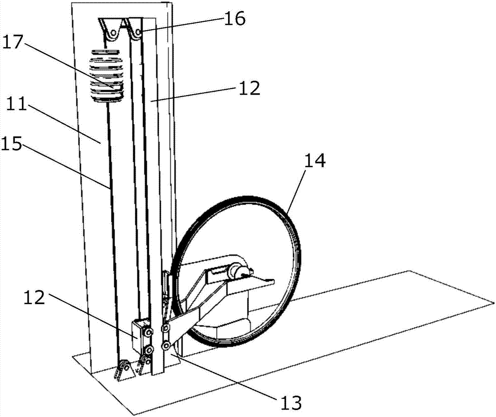
[0035] image 3 It is a structural schematic diagram of the second embodiment of the present invention. As shown in the figure, the bicycle parking pile includes a column 11 and a traction system. The column is provided with a lifting rail groove 12 and a wheel lock 12. And the pulley 16; the wheel lock 23 is connected with the traction system; the pulley 16 is arranged on the upper end of the column, the rope is arranged on the pulley, and the rope is connected to the wheel lock 12 and the counterweight 17 respectively.
[0036] Figure 4 Shown is a schematic structural diagram of the wheel lock of the second embodiment. As shown in the figure, the wheel lock 12 includes a fixed end 121 and two extension arms 123; The column moves up and down; the front end of the extension arm is provided with a slope 124, and the rear end of the slope is provided with a concave platform 125.
[0037] When the bicycle wheel is moving forward, its axle will first contact the slope 124 and a...
no. 3 example
[0042] Figure 5-8 The third embodiment of the present invention is illustrated, and the same parts as the first embodiment and the second embodiment will not be described again. Such as Figure 5 As shown, the wheel lock is provided with a contact slope 124' and a concave platform 125', the wheel bearing is clamped on the sunken platform 125' to realize locking, the wheel lock is also provided with a lower clamping plate 1211, and a hook is provided below the system switch 13 .
[0043] Image 6 It is a structural schematic diagram of the system switch of the present invention, which includes a push rod 131, a rotating shaft 132, a hook 133, and a base 134. After the wheel touches the push rod 131, the switch will rotate around the rotating shaft 132, and the hook and the bottom of the sinking lock The clamping plate 133 is disengaged, and the switch is turned on.
[0044] Figure 7 It is a schematic diagram of the structure of the fixed end of the wheel lock in this emb...
PUM
 Abstract
Description
Claims
Application Information
 - R&D
- Intellectual Property
- Life Sciences
- Materials
- Tech Scout
- Unparalleled Data Quality
- Higher Quality Content
- 60% Fewer Hallucinations
Browse by: Latest US Patents, China's latest patents, Technical Efficacy Thesaurus, Application Domain, Technology Topic, Popular Technical Reports.
© 2025 PatSnap. All rights reserved.Legal|Privacy policy|Modern Slavery Act Transparency Statement|Sitemap|About US| Contact US: help@patsnap.com


