
A Grinding Gap and Anti-Collision Method Based on Power Signal

A power signal and anti-collision technology, which is applied to the parts of grinding machine tools, grinding/polishing equipment, grinding automatic control devices, etc. In order to improve the efficiency of grinding process and the quality of grinding process

Inactive Publication Date: 2019-04-19
UNIV OF SHANGHAI FOR SCI & TECH
View PDF4 Cites 0 Cited by
  • Summary
  • Abstract
  • Description
  • Claims
  • Application Information

AI Technical Summary

Problems solved by technology

[0004] The invention aims at the problem that the grinding power signal will drift along with the running time of the main shaft, which will affect the function of grinding lost motion, and proposes a grinding lost motion and anti-collision method based on the power signal, using an automatic detection power sensor Whether it is normal with the data acquisition card to prevent the failure of the empty space, through the interaction between the numerical control system of the CNC machine tool and the data acquisition card to avoid the impact of the grinding wheel of the machine tool spindle at the empty space speed within the entire workpiece blank margin, through the delay of the control signal The setting solves the problem of the failure of the void elimination caused by the irregular shape of the grinding workpiece blank

Method used


Image

  • A Grinding Gap and Anti-Collision Method Based on Power Signal
  • A Grinding Gap and Anti-Collision Method Based on Power Signal
  • A Grinding Gap and Anti-Collision Method Based on Power Signal

Examples


Embodiment Construction

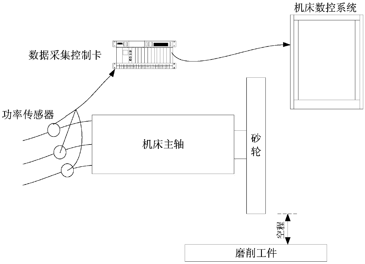
[0017] Such as figure 1 As shown in the diagram of the void elimination and anti-collision monitoring system, the power sensor is installed at the output end of the machine tool spindle inverter, and the data acquisition control card is connected to the signal line of the power sensor, and the following 1), 2), 3), 4 ), 5) and 6) steps are embedded in the data acquisition control card, and the switch input / output of the data acquisition control card is connected with the numerical control system of the CNC machine tool, and the machining cycle program of the CNC machine tool is started to complete the void elimination / anti-collision function.

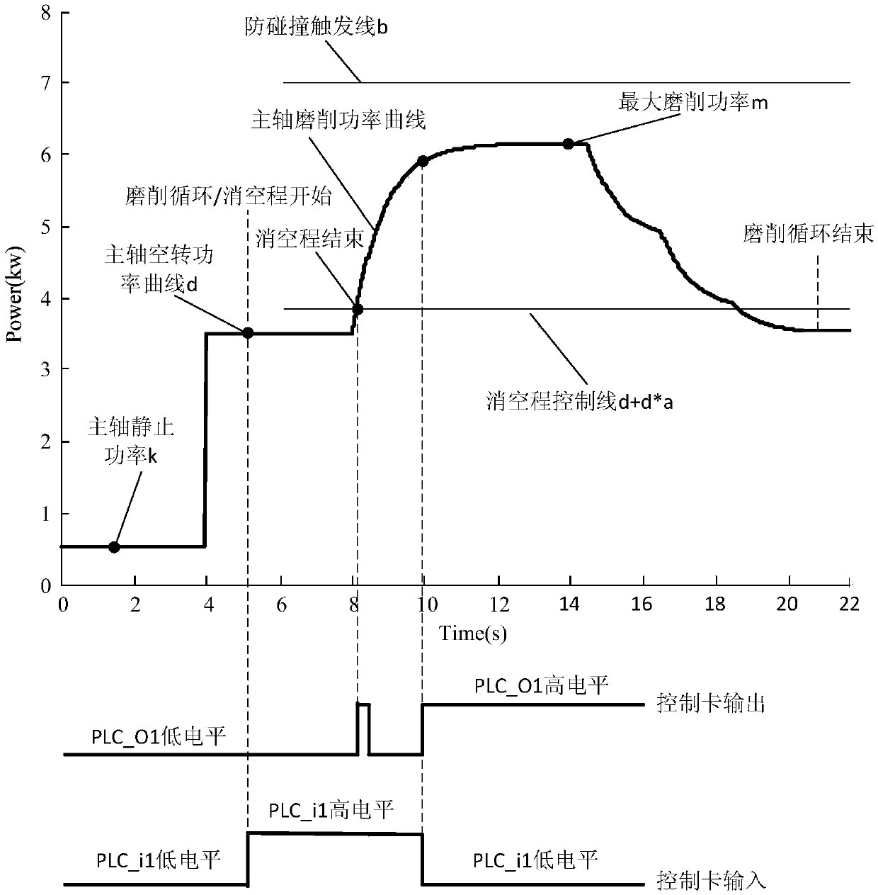
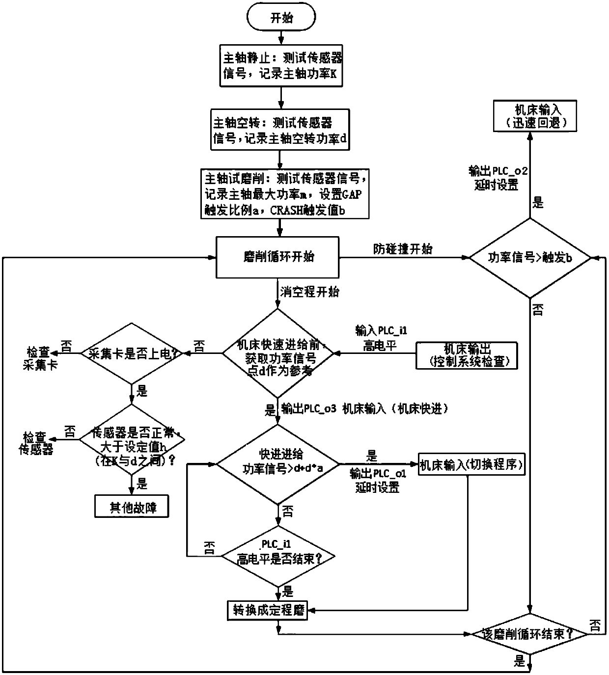
[0018] Such as figure 2 The schematic diagram of the blanking distance monitoring power signal and the input / output signal of the control card shown is image 3 The flow chart of the realization of void elimination and anti-collision shown in the figure, the realization of the grinding void elimination and anti-collision method based ...


PUM


Abstract

The invention relates to a grinding idle stroke elimination and collision prevention method based on power signals. The method comprises the steps of sampling the static power k of a spindle; sampling the idling power d of the spindle; sampling the maximum power m of trial grinding of the spindle; setting a reference set value h according to the power signals, wherein the value of h is between the value of k and the value of d; setting a proportion coefficient a determined according to the difference value between the maximum power m of trial grinding and the idling power d of the spindle, and setting up an idle stroke elimination control line d+d*a relative to d; and setting a collision prevention control line b, wherein b is greater than m. The multiple control lines are set, and a numerical control system of a numerical control machine tool and a data acquisition card interact to prevent a grinding wheel of the machine tool spindle from impacting at the idle stroke speed in the whole margin of a workpiece blank; due to time delay of control signals, the problem that idle stroke elimination fails because the shape of the ground workpiece blank is irregular is solved; and whether a power sensor and the data acquisition card are normal or not is automatically detected to prevent failures of idle stroke elimination. The method has important significance for improving the grinding machining efficiency and the grinding machining quality.

Description

technical field [0001] The invention relates to a machine tool control technology, in particular to a grinding space elimination and anti-collision method based on a power signal. Background technique [0002] Grinding and anti-collision are commonly used methods in grinding processing to improve the efficiency of grinding and improve the safety measures of machine tools. At present, there are many companies in the market specializing in the production of grinding and anti-collision systems, such as Marposs in Italy. companies, SBS companies in the United States, etc., and most of these companies use acoustic emission sensor signals to perform grinding and anti-collision. Due to the high requirements for the installation conditions of the acoustic emission signal, high cost, and easy to be affected by the external environment, it is difficult to apply it in many grinding processing occasions. [0003] The actual grinding process shows that compared with the acoustic emissio...

Claims


Application Information

Patent Timeline
Patent Type & Authority Patents(China)
IPC IPC(8): B24B51/00B24B55/00G05B19/05
CPCB24B51/00B24B55/00G05B19/054
Inventor 迟玉伦李郝林
Owner UNIV OF SHANGHAI FOR SCI & TECH
Learn More