
Beam forming-optimizing method and device

A technology of beamforming and optimization methods, which is applied in the field of beamforming optimization methods and devices, and can solve problems such as large errors, slow convergence speed, and unsatisfactory effects

Inactive Publication Date: 2017-12-12
MEIZU TECH CO LTD
View PDF6 Cites 6 Cited by
  • Summary
  • Abstract
  • Description
  • Claims
  • Application Information

AI Technical Summary

Problems solved by technology

But these two algorithms have their own limitations: the non-blind estimation algorithm needs reference signals, such as training sequences or pilots, that is, the receiving end knows the reference signals in advance, and then determines the value of each array element according to the received results. Channel response, which determines the channel matrix of the antenna array and the direction of arrival of the signal, and then uses the algorithm to adaptively adjust the weighted value according to certain criteria
Although the blind estimation algorithm does not waste the signal bandwidth, its error is large, the convergence speed is slow, and it is easy to miscalculate the small extreme points, especially in the fast time-varying channel environment, the effect is not ideal

Method used


Image

  • Beam forming-optimizing method and device
  • Beam forming-optimizing method and device
  • Beam forming-optimizing method and device

Examples


Embodiment Construction

[0074] In order to make the purpose, technical solutions and advantages of the embodiments of the present invention clearer, the technical solutions in the embodiments of the present invention will be clearly and completely described below in conjunction with the drawings in the embodiments of the present invention. Obviously, the described embodiments It is a part of embodiments of the present invention, but not all embodiments. Based on the embodiments of the present invention, all other embodiments obtained by persons of ordinary skill in the art without making creative efforts belong to the protection scope of the present invention.

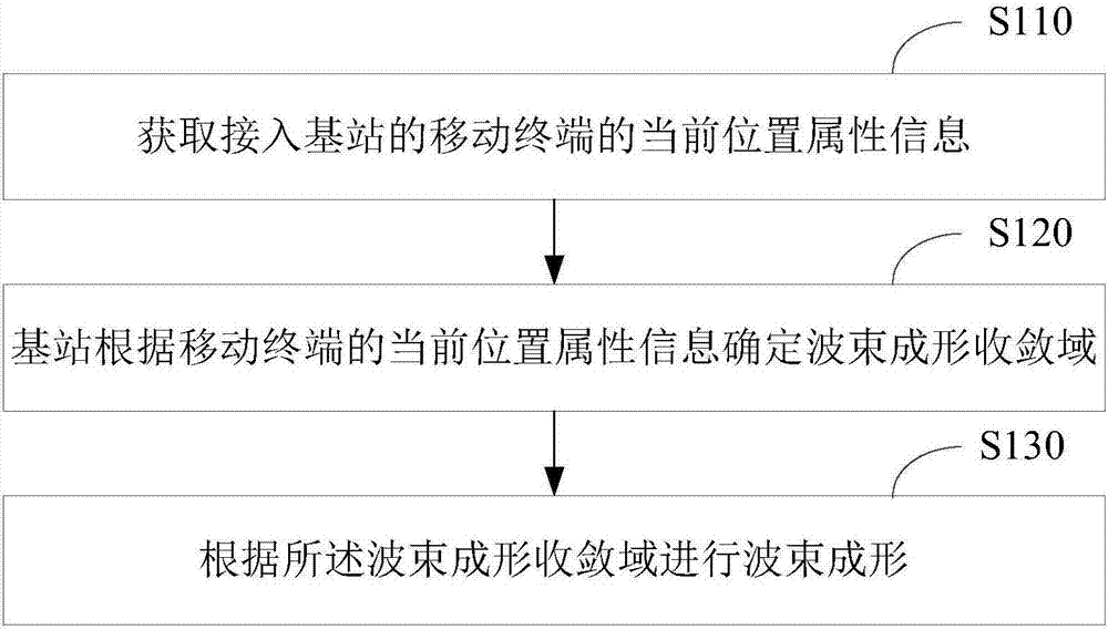
[0075] See figure 1 , shows a flowchart of a beamforming optimization method according to an embodiment of the present application. The method is applied to a base station. The base station uses an array antenna, and the array antenna can generate directional beams for one or more specific directions in space. Such as figure 1 As shown, the...


PUM


Abstract

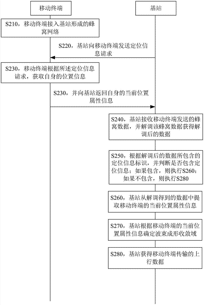
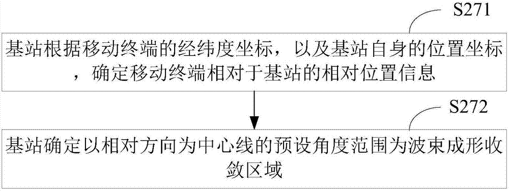
The invention provides a beam forming-optimizing method and device. A base station acquires current position property information of an accessed mobile terminal, and performs beam forming under the assistance of the current position property information of the mobile terminal. The base station determines a general direction of a signal incoming wave according to the current position of the mobile terminal, so that a scanning range of a beam direction is reduced; the convergence domain of the beam forming is reduced; and the aim of accelerating the convergence speed of the beam forming is fulfilled.

Description

technical field [0001] The invention belongs to the technical field of antennas, and in particular relates to a beamforming optimization method and device. Background technique [0002] Beamforming is the combination of antenna technology and digital signal processing technology for directional signal transmission or reception. Beamforming uses an array antenna. An array antenna is an antenna system composed of many identical individual antennas (for example, symmetrical antennas) arranged in a certain order, also known as an antenna array. The independent units of the antenna array are called array elements or antenna units. After properly weighting the input and output of each array element in the array antenna, the antenna array can generate directional beams in one or more specific directions in space, that is, the pattern of the antenna array can be changed, and its directivity can be controlled , so as to effectively track useful signals and suppress interference and ...

Claims


Application Information

Patent Timeline
Patent Type & Authority Applications(China)
IPC IPC(8): H04B7/08H04W4/02H04W64/00
CPCH04B7/086H04W4/025H04W64/006
Inventor 王际玮
Owner MEIZU TECH CO LTD
Learn More