
Drying and sterilizing cabinet

A technology of disinfection cabinet and disinfection lamp, applied in drying, disinfection, dryer and other directions, can solve the problem of inconvenient wiring of disinfection lamp

Active Publication Date: 2017-12-12
ZHONGSHAN KINGCARE ELECTRICAL TECH CO LTD
View PDF7 Cites 3 Cited by
  • Summary
  • Abstract
  • Description
  • Claims
  • Application Information

AI Technical Summary

Problems solved by technology

[0003] The technical problem to be solved by the present invention is to provide a drying and disinfection cabinet, which can solve the problem of inconvenient wiring of the disinfection lamp in the current drying and disinfection cabinet.

Method used


Image

  • Drying and sterilizing cabinet
  • Drying and sterilizing cabinet
  • Drying and sterilizing cabinet

Examples


Embodiment 1

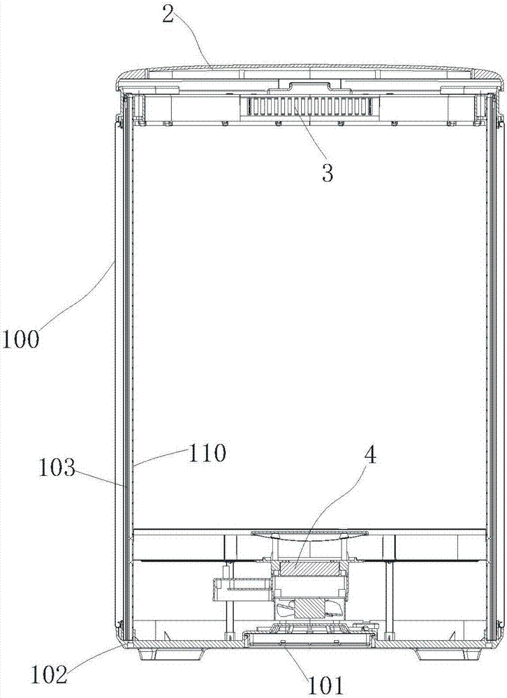
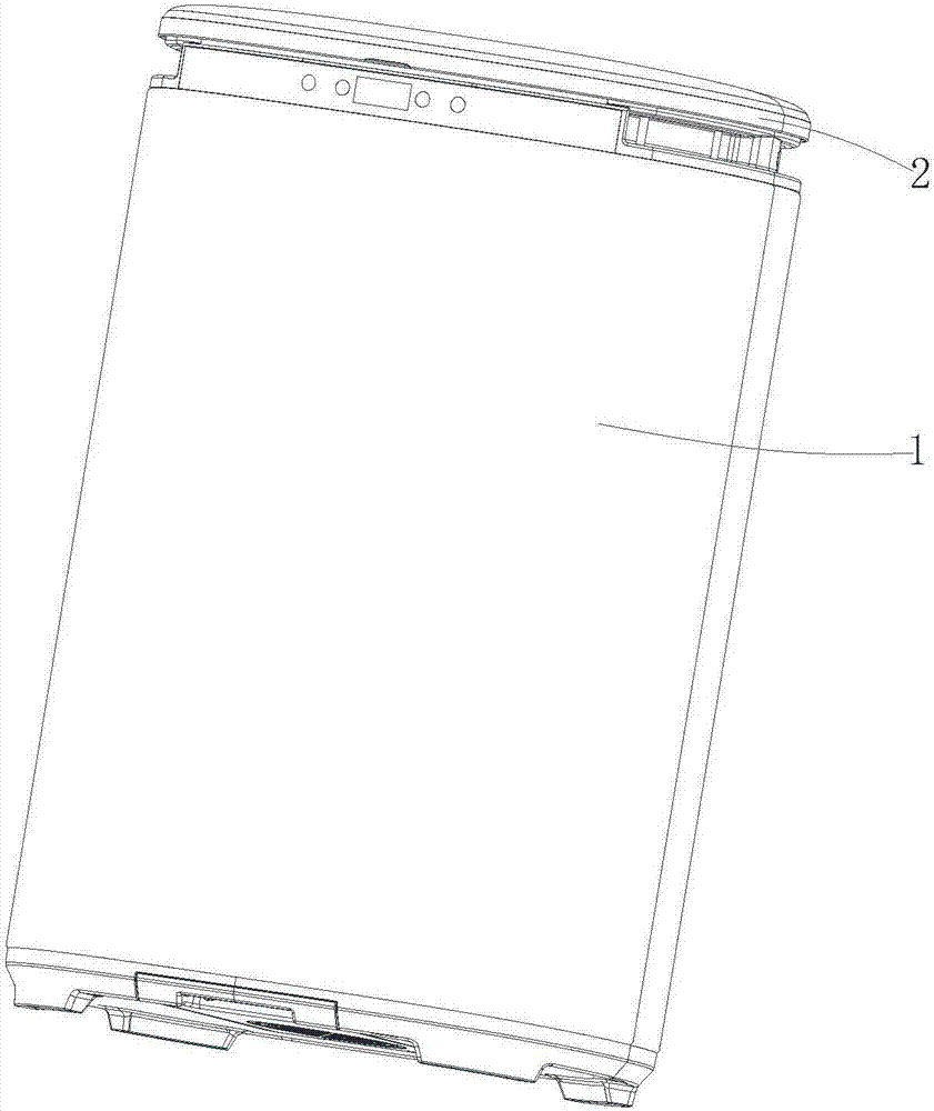
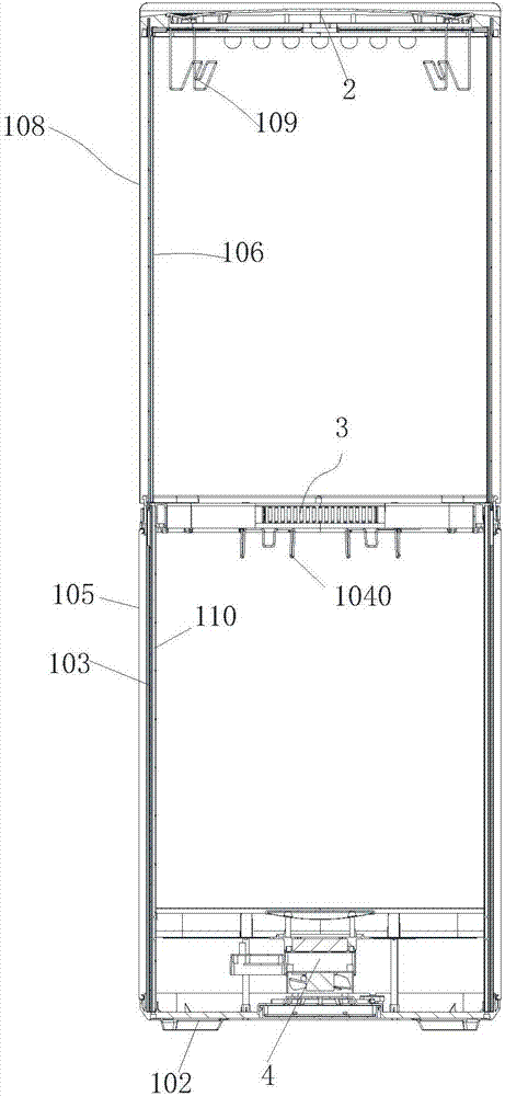
[0033] Such as figure 1 , 2 As shown in and 5, the drying disinfection cabinet includes a disinfection cabinet main body 1 and a cover body 2 covered with the disinfection cabinet main body 1; one end of the cover body 2 is rotationally connected with the disinfection cabinet main body 1. The disinfection lamp 3 is arranged on the upper end of the inner side of the disinfection cabinet main body 1; the disinfection cabinet main body 1 includes an outer shell 100 and an inner container 110 arranged in the outer shell 100; Institution 4. The bottom 100 of the shell is provided with an air inlet 101, and the bottom of the liner 110 is provided with a ventilation hole 111; the air inlet of the hot air mechanism 4 communicates with the air inlet 101, and the hot air mechanism 4 The air outlet is in communication with the ventilation hole 111. When it is necessary to dry and sterilize the object, the object can be put into the inner container, and the cover body 2 is covered. Th...

Embodiment 2

[0041] Such as image 3 , 4, 8 and 10, the drying disinfection cabinet includes a disinfection cabinet main body 1 and a cover body 2 that is closed with the disinfection cabinet main body 1; a disinfection lamp 3 is located at the upper end of the inner side of the disinfection cabinet main body 1; 1 includes an outer shell 100 and an inner container 110 inside the outer shell 100; a hot air mechanism 4 is provided between the outer shell 100 and the inner container 110. The bottom 100 of the shell is provided with an air inlet 101, and the bottom of the liner 110 is provided with a ventilation hole 111; the air inlet of the hot air mechanism 4 communicates with the air inlet 101, and the hot air mechanism 4 The air outlet is in communication with the ventilation hole 111. When it is necessary to dry and sterilize the object, the object can be put into the inner container, and the cover body 2 is covered. The hot air mechanism 4 continuously blows hot air into the inner co...


PUM


Abstract

The invention discloses a drying and sterilizing cabinet, which comprises a sterilizing cabinet body and a cover body covering the sterilizing cabinet body. A sterilizing lamp is arranged at the upper end of the inner side of the sterilizing cabinet body; the sterilizing cabinet body comprises a shell and an inner container arranged in the shell; a hot air mechanism is arranged between the shell and the inner container; an air inlet hole is formed in the bottom end of the shell; a vent hole is formed in the bottom end of the inner container; an air inlet of the hot air mechanism communicates with the air inlet hole; and an air outlet of the hot air mechanism communicates with the vent hole. The sterilizing lamp is arranged at the upper end of the inner side of the sterilizing cabinet body, so that an electric wire for supplying power to the sterilizing lamp is conveniently installed, and has no need to be bent continuously along with the turning of the cover body so as to be protected.

Description

technical field [0001] The invention relates to the field of drying equipment, in particular to a drying and disinfection cabinet. Background technique [0002] The invention patent of the Chinese patent "Patent No.: CN201620246739.5, the patent name is an electrical appliance that can be dried and sterilized at the same time" solves the problem that the existing dryer does not have the functions of disinfection, deodorization and quality preservation, and It can only be used for drying and disinfection of towels, and has a single purpose, and the appearance is not beautiful enough, and the installation is not convenient enough; The wires for power supply also need to follow the rotation. If they are not tight, it will cause inconvenience to the installation of the wires, and it will easily cause the wires to be bent and broken multiple times. In view of the above defects, it is necessary to design a drying and disinfection cabinet. Contents of the invention [0003] The...

Claims


Application Information

Patent Timeline
Patent Type & Authority Applications(China)
IPC IPC(8): F26B9/06F26B21/00A61L2/10A61L2/26
CPCA61L2/10A61L2/26F26B9/06F26B21/001F26B21/004A61L2202/26A61L2202/23
Inventor 刘忠海
Owner ZHONGSHAN KINGCARE ELECTRICAL TECH CO LTD
Learn More